MR8740T_Quick guide_eng_20191016H.pdf - 第32页
26 Screen 1.3 Screen A commercially-available monitor is required to display information. Use a monitor that supports a VGA input, HDMI input, or DisplayPort input. (Full HD with a resolution of 1920 × 1080 dots is recom…
25
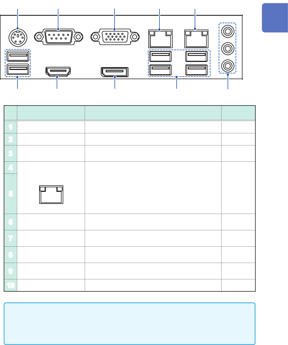
Name and Function of Each Part
3
1
5
6
4
7 8
10
9
2
No. Name Function
Reference
page
1
PS2 connector Not available –
2
COM terminal Not available –
3
VGA terminal
Connect a display with an RGB cable.
Maximum resolution: 2560 × 1600
–
4
1000BASE-T connector
LINK ACT
Attach a LAN cable to connect the instrument to your
network.
ACT LED
Blinking: Communicating data
LINK LED
Yellow light: 1000BASE
Green light: 100BASE
Off: 10BASE
p. 55
5
6
USB2.0 connector
Connect a USB ash drive, USB mouse, or USB
keyboard.
p. 57
7
HDMI terminal
Connect a display with an HDMI cable.
Maximum resolution: 3840 × 2160
–
8
DisplayPort* terminal
Connect a display with a DisplayPort cable.
Maximum resolution: 4096 × 2160
–
9
USB3.0 connector
Connect a USB ash drive, USB mouse, or USB
keyboard.
p. 57
10
Audio terminal Not available –
• A resolution of 1920 × 1080 dots or more is recommended. Using a display with a lower
resolution can cause poor visibility of waveforms.
• Using a 4K-resolution monitor connected to the HDMI or DisplayPort terminal with the
maximum resolution set may require longer time for processing command communication and
displaying screens.
*: Trademark of another company
1
Overview
26
Screen
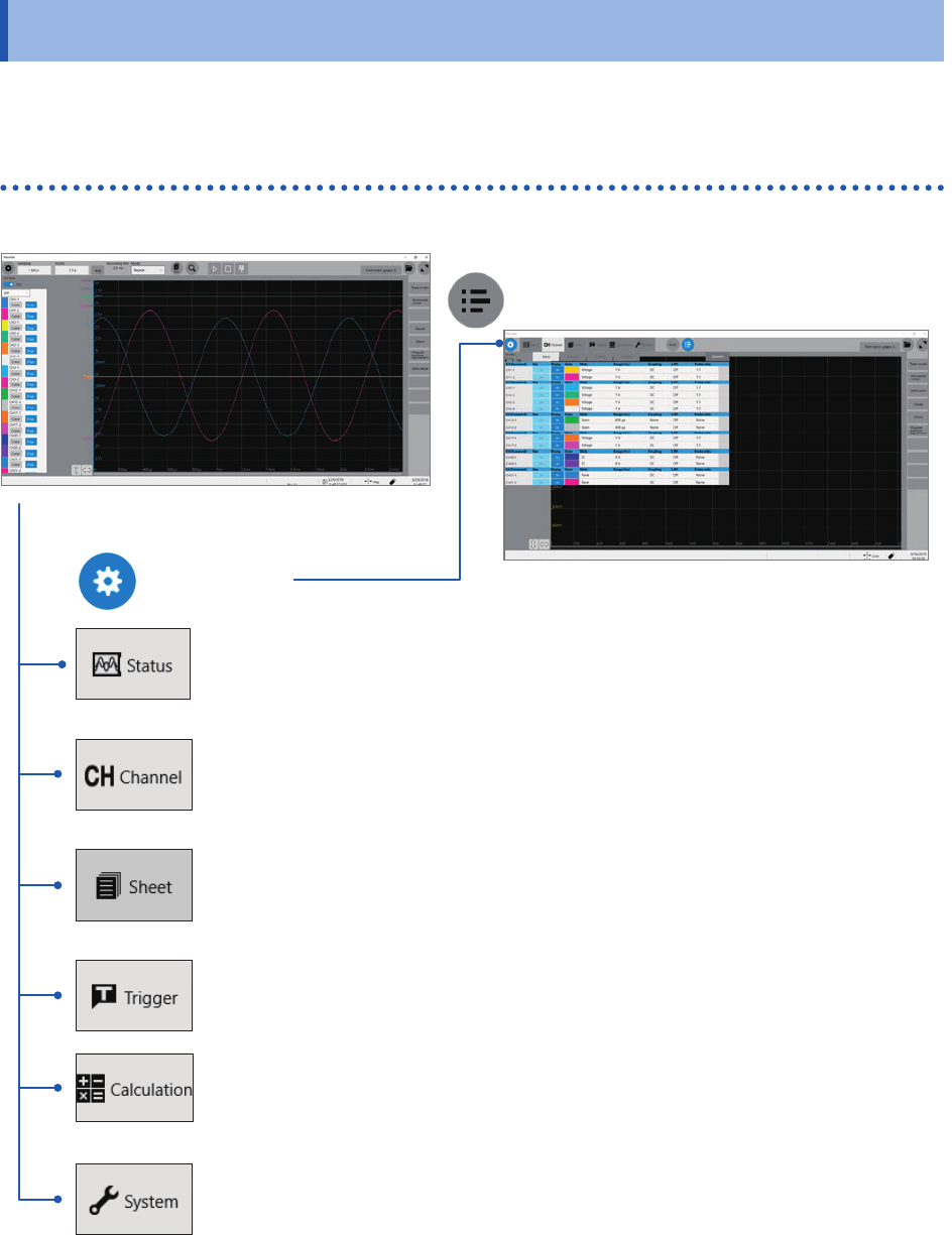
1.3 Screen
A commercially-available monitor is required to display information. Use a monitor that supports a VGA
input, HDMI input, or DisplayPort input. (Full HD with a resolution of 1920 × 1080 dots is recommended)
Screen conguration
Status
This screen is used to set the measurement conditions such as the sampling rate,
recording length (shot), and saving data.
Refer to “3.2 Setting Measurement Conditions” (p. 68).
Channel
This screen is used to congure the input channel settings such as the measurement
range and low-pass lter.
Refer to “3.3 Conguring the Input Channel settings” (p. 70).
Sheet screen
This screen is used to congure a display settings for each sheet.
Choose channels to be displayed on each sheet.
Refer to “1.4 Conguring the Sheet Settings” of the Instruction Manual.
Trigger
This screen is used to congure the trigger settings.
Refer to “3.4 Conguring the Level Trigger Settings” (p. 73).
Calculation screen
This screen is used to congure the numerical and waveform calculation settings.
Refer to “7 Numerical Calculation Functions” and “8 Waveform Calculation”in Instruction
Manual.
System screen
This screen is used to congure the system environment, communications, and external
control terminal settings, and to initialize the instrument. You can also check the
instrument conguration on this screen.
Refer to “6.2 Initializing the Instrument” (p. 147).
Waveform screen (p. 27)
List screen
Setting screen
27
Screen
Explanation of each screen
10
1213
11
1
2
8 9
43 5 6 7
14
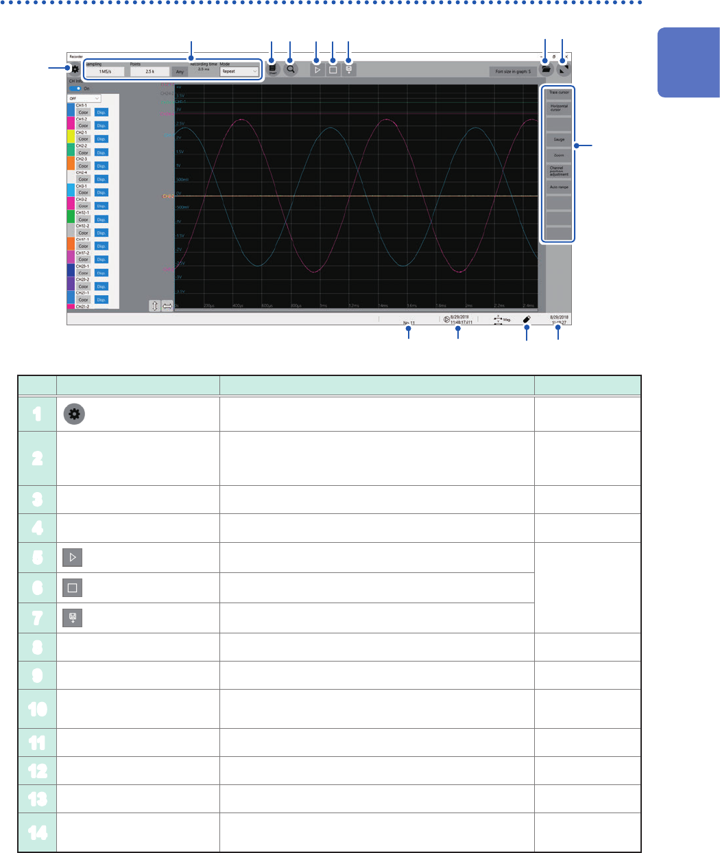
Waveform screen
No. Item Description Reference page
1
Switches between the setting and waveform screens. p. 68, p. 81
2
Measurement condition
setting
Allows you to choose a sampling rate, recording length
(the number of points and user-dened length), and
recording mode (single or repeat).
p. 68
3
Sheet selection Switches among preset sheets. *
1
4
Search setting screen Allows you to set search conditions. *
2
5
(Start icon)
Starts a measurement.
p. 75
6
(Stop icon)
Stops the measurement.
7
(Save icon)
Saves data.
8
File screen Opens the le screen. *
3
9
Waveform area zoom-in Zooms in the waveform area. –
10
Function buttons
Allows you to choose functions available on the
waveform screen.
p. 81
11
Current date and time Displays the current date and time. p. 62
12
Eject button Ejects a USB ash drive. p. 58
13
Trigger time Displays the trigger time. –
14
Number of measurement
times
Displays the processing state of the instrument.
Displays the number of measurement times.
–
*1: Refer to “1.4 Specifying the Sheet Settings” of Instruction Manual.
*2: Refer to “6 Search Function” of Instruction Manual.
*3: Refer to “4 Saving/Loading Data and Managing Files” of Instruction Manual.
1
Overview