MR8740T_Quick guide_eng_20191016H.pdf - 第31页
25 Name and Function of Each Part 3 1 5 6 4 7 8 10 9 2 No. Name Function Reference page 1 PS2 connector Not available – 2 COM terminal Not available – 3 VGA terminal Connect a display with an RGB cable. Maximum resolutio…
24
Name and Function of Each Part
Instrument status indicator
The LEDs indicate the instrument status.
Basic LED indicator
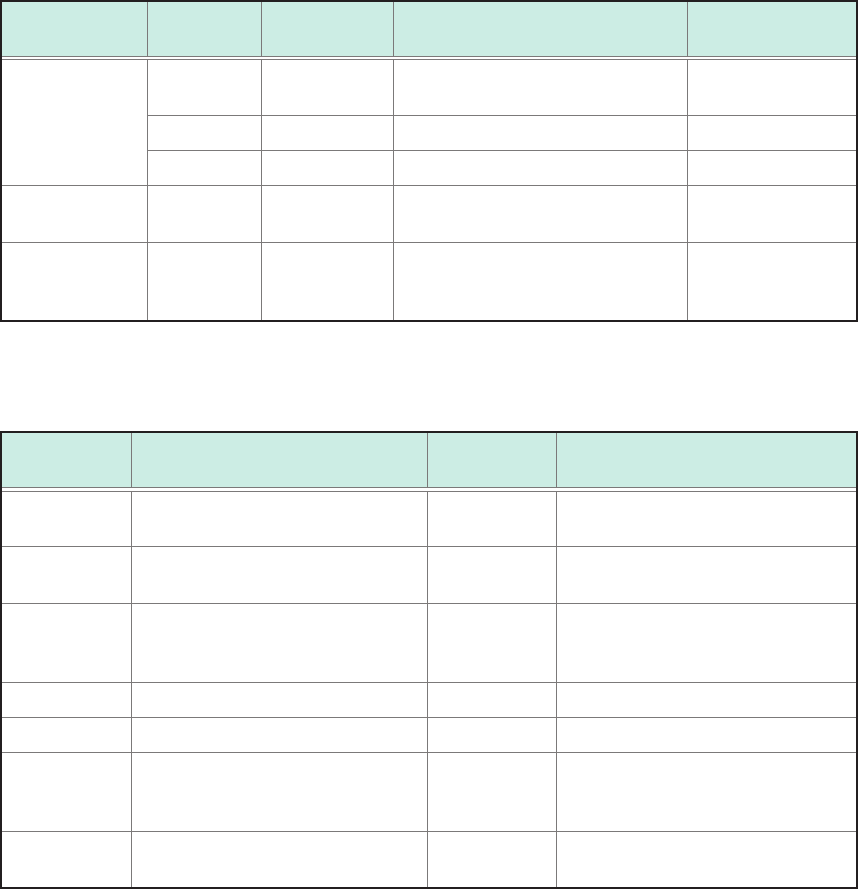
LED name Color Lighting up /
blinking
When lights up How to turn off
the LED
POWER
STANDBY
Orange Lighting up Stand-by status Set the rear switch
to off.
Green Lighting up Power-on status Shut the power off.
Green Blinking Power-on status (warm-up) Shut the power off.
DIAG Refer to the
table below.
Refer to the
table below.
Refer to the table below.
–
CMD ERR Red Lighting up A command received contained a
syntax error.
Send the
*CLS
command to turn
off the LED.
Details of DIAG LED
DIAG LED mode table
Indicator
priority order
Status Color Note
1 The inside temperature is high
(ambient temperature > 35°C).
Red
–
2 The inside temperature is low
(ambient temperature < 10°C).
Purple
–
3 CPU load rate ≥ 80% Yellow Updated every 0.5 seconds, based
on average load rates calculated
over the period.
4 Waiting for a trigger. Blue –
4 The recording is in progress. Green –
4 The recording is complete. Pink Switches to the normal operation
indication when a new command is
received.
5 During normal operation (under
suspension)
White
–
25
Name and Function of Each Part
3
1
5
6
4
7 8
10
9
2
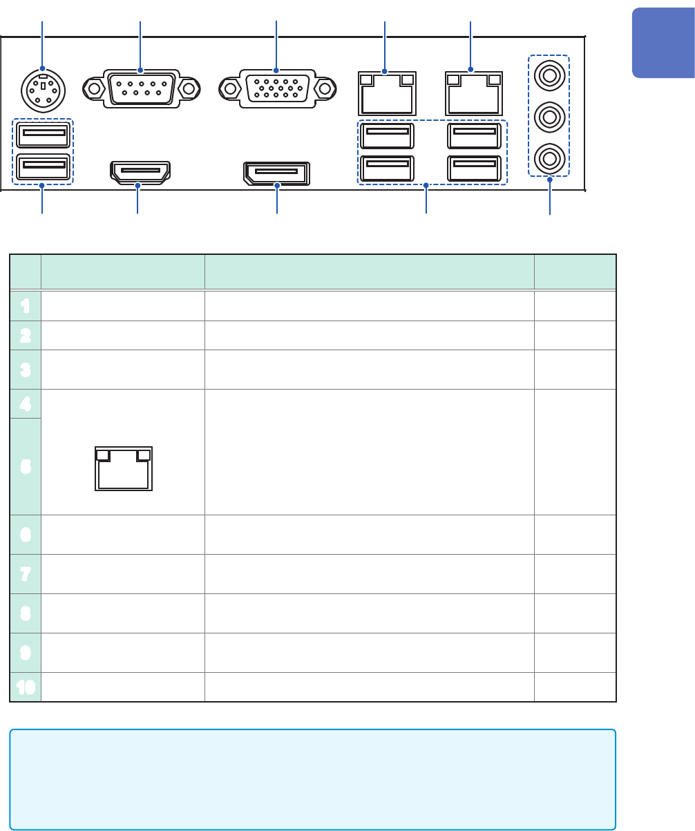
No. Name Function
Reference
page
1
PS2 connector Not available –
2
COM terminal Not available –
3
VGA terminal
Connect a display with an RGB cable.
Maximum resolution: 2560 × 1600
–
4
1000BASE-T connector
LINK ACT
Attach a LAN cable to connect the instrument to your
network.
ACT LED
Blinking: Communicating data
LINK LED
Yellow light: 1000BASE
Green light: 100BASE
Off: 10BASE
p. 55
5
6
USB2.0 connector
Connect a USB ash drive, USB mouse, or USB
keyboard.
p. 57
7
HDMI terminal
Connect a display with an HDMI cable.
Maximum resolution: 3840 × 2160
–
8
DisplayPort* terminal
Connect a display with a DisplayPort cable.
Maximum resolution: 4096 × 2160
–
9
USB3.0 connector
Connect a USB ash drive, USB mouse, or USB
keyboard.
p. 57
10
Audio terminal Not available –
• A resolution of 1920 × 1080 dots or more is recommended. Using a display with a lower
resolution can cause poor visibility of waveforms.
• Using a 4K-resolution monitor connected to the HDMI or DisplayPort terminal with the
maximum resolution set may require longer time for processing command communication and
displaying screens.
*: Trademark of another company
1
Overview
26
Screen
1.3 Screen
A commercially-available monitor is required to display information. Use a monitor that supports a VGA
input, HDMI input, or DisplayPort input. (Full HD with a resolution of 1920 × 1080 dots is recommended)
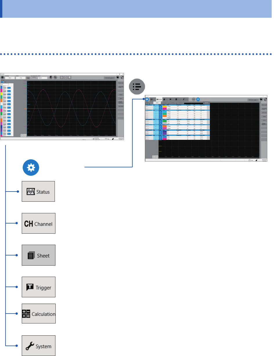
Screen conguration
Status
This screen is used to set the measurement conditions such as the sampling rate,
recording length (shot), and saving data.
Refer to “3.2 Setting Measurement Conditions” (p. 68).
Channel
This screen is used to congure the input channel settings such as the measurement
range and low-pass lter.
Refer to “3.3 Conguring the Input Channel settings” (p. 70).
Sheet screen
This screen is used to congure a display settings for each sheet.
Choose channels to be displayed on each sheet.
Refer to “1.4 Conguring the Sheet Settings” of the Instruction Manual.
Trigger
This screen is used to congure the trigger settings.
Refer to “3.4 Conguring the Level Trigger Settings” (p. 73).
Calculation screen
This screen is used to congure the numerical and waveform calculation settings.
Refer to “7 Numerical Calculation Functions” and “8 Waveform Calculation”in Instruction
Manual.
System screen
This screen is used to congure the system environment, communications, and external
control terminal settings, and to initialize the instrument. You can also check the
instrument conguration on this screen.
Refer to “6.2 Initializing the Instrument” (p. 147).
Waveform screen (p. 27)
List screen
Setting screen