MR8740T_Quick guide_eng_20191016H.pdf - 第17页
11 Operation Precautions Rating of generator modules Y ou can mixedly install generator modules and measurement modules in the instrument. Intended use Model name Number of channels Maximum output frequency Output voltag…
10
Operation Precautions
Handling the instrument and modules
DANGER
• Do not use the modules or the cables to measure circuits that exceed those
ratings or specications. Damage to the instrument or overheating can cause
bodily injury.
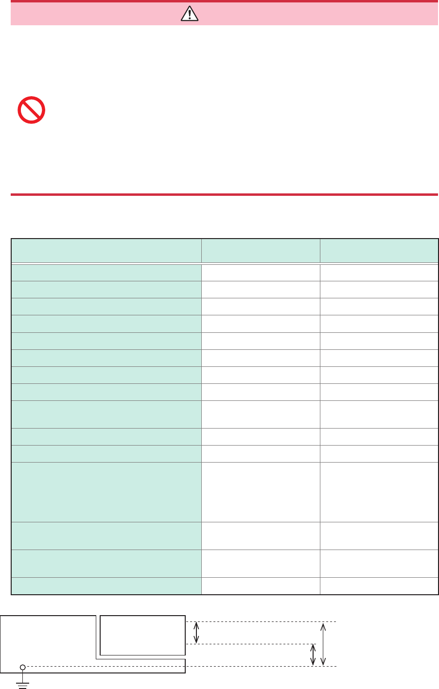
• The maximum input voltage and maximum rated voltage to earth of the modules
and connection cords are shown in the following table. To avoid an electric
shock and damage to the instrument, ensure that input voltage never exceeds
these limits. The lower maximum input voltage of the module or connection
cord must be used. Measuring a voltage exceeding this value can cause
damage to the instrument, resulting in bodily injury. The same applies to the
maximum rated voltage to earth using an input attenuator for the measurement.
Ensure that the connection does not allow the input voltage to exceed the
maximum rated voltage to earth.
Refer to “5.2 Specications of the Options” (p. 101).
Rating of input modules
Modules Maximum input voltage
Maximum rated voltage to
earth
Model 8966 Analog Unit 400 V DC 300 V AC/DC (CAT II)
Model 8967 Temp Unit – 300 V AC/DC (CAT II)
Model 8968 High Resolution Unit 400 V DC 300 V AC/DC (CAT II)
Model U8969 Strain Unit – 30 V rms / 60 V DC
Model 8970 Freq Unit 400 V DC 300 V AC/DC (CAT II)
Model 8971 Current Unit – Non-isolated
Model 8972 DC/RMS Unit 400 V DC 300 V AC/DC (CAT II)
Model 8973 Logic Unit – Non-isolated
Model U8974 High Voltage Unit
1000 V DC
700 V AC
1000 V AC/DC (CAT III)
600 V AC/DC (CAT IV)
Model U8975 4ch Analog Unit 200 V DC 300 V AC/DC (CAT II)
Model U8977 3CH Current Unit – Non-isolated
Model U8978 4CH Analog Unit
40 V DC (Direct input)
400 V DC (with Model 9665
10:1 Probe used)
30 V AC, 60 V DC
(Direct input)
300 V AC/DC (CAT II)
(with Model 9665 10:1
Probe used)
Model U8979 Charge Unit 40 V DC
30 V AC
60 V DC
Model
MR8990
Digital Voltmeter Unit 500 V DC 300 V AC/DC (CAT II)
Model U8991 Digital Voltmeter Unit 100 V DC 100 V AC/DC
ModulesModel MR8740T
High
Low
Maximum input voltage
Maximum rated voltage
to earth
11
Operation Precautions
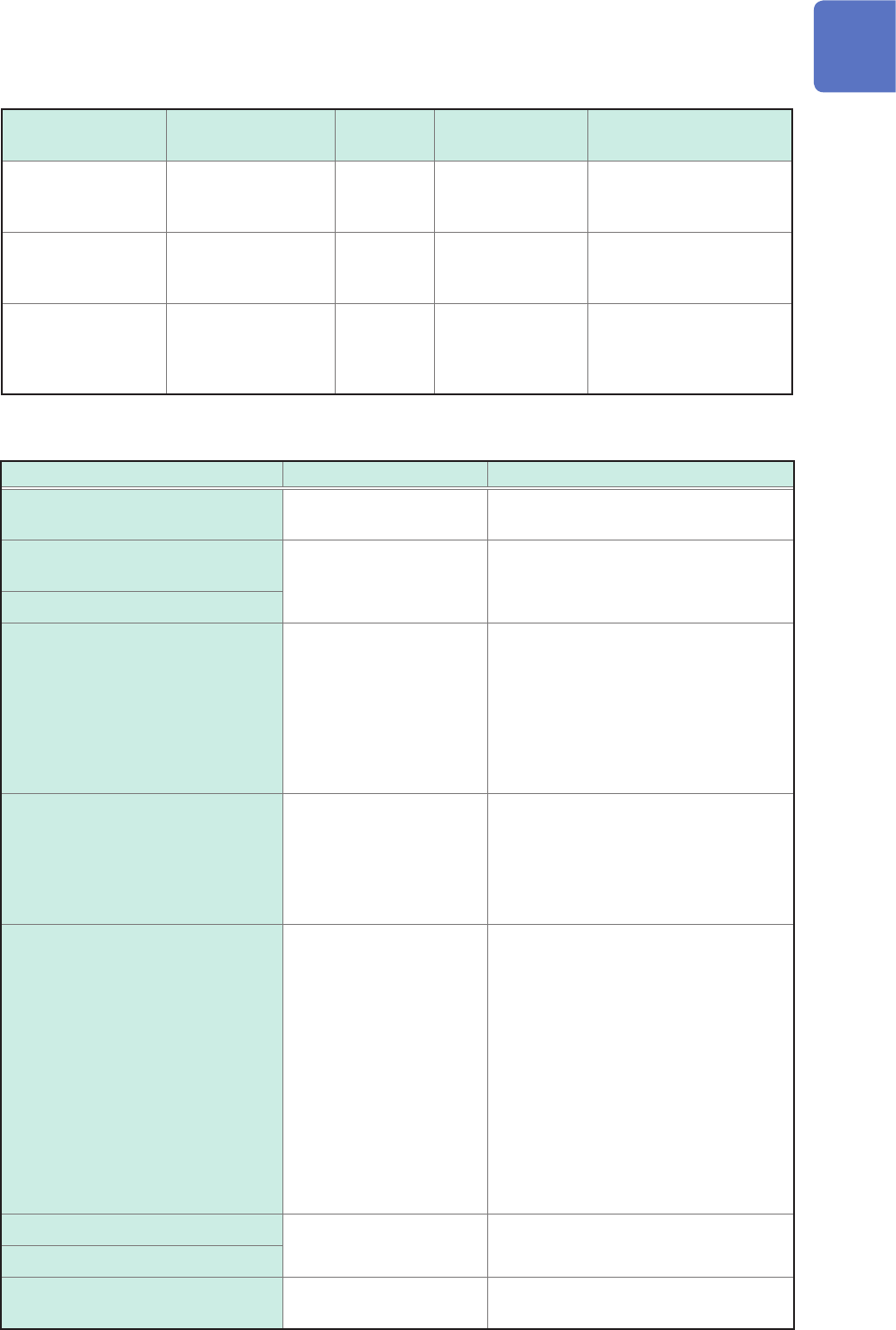
Rating of generator modules
You can mixedly install generator modules and measurement modules in the instrument.
Intended use Model name Number of
channels
Maximum output
frequency
Output voltage
For generating sine
wave and DC
Model MR8790
Waveform Generator
Unit
4 20 kHz −10 V to 10 V
For generating pulse
Model MR8791
Pulse Generator Unit
8 20 kHz
TTL level
(amplitude: 0 to 5 V)
Open-collector output
For generating DC
voltage, DC current,
and resistance
generation
Model U8794
VIR Generator Unit
8
Voltage: −0.1 V to 5.3 V
Current: −5 mA to 5 mA
Resistance: 10
Ω
to 1 M
Ω
Ratings of connection cords
Connection Cord Maximum input voltage Maximum rated voltage to earth
Model L9197 Connection Cord 600 V AC/DC
600 V AC/DC (CAT III)
300 V AC/DC (CAT IV)
Model L9198 Connection Cord
(for measuring low-voltage)
300 V AC/DC
600 V AC/DC (CAT II)
300 V AC/DC (CAT III)
Model L9217 Connection Cord
Model L9790 Connection Cord 600 V AC/DC
• With Model L9790-01 Alligator Clip or
Model 9790-03 Contact Pin attached
600 V AC/DC (CAT II)
300 V AC/DC (CAT III)
• With Model 9790-02 Grabber Clip
attached
300 V AC/DC (CAT II)
150 V AC/DC (CAT III)
Model 9322 Differential Probe
2000 V DC
1000 V AC
• With grabber clips attached
1500 V AC/DC (CAT II)
600 V AC/DC (CAT III)
• With alligator clips attached
1000 V AC/DC (CAT II)
600 V AC/DC (CAT III)
Model L4940 Connection Cord 1000 V DC*
• With Model L4935 Alligator Clip Set or
Model L4932 Test Pin Set attached
600 V AC/DC (CAT IV)
1000 V AC/DC (CAT III)
• With Model 9243 Grabber Clip or
Model L4936 Bus Bar Clip Set attached
600 V AC/DC (CAT III)
• With Model L4937 Magnetic Adapter
Set attached
1000 V AC/DC (CAT III)
• With Model L4934 Small Alligator Clip
Set attached
300 V AC/DC (CAT III)
600 V AC/DC (CAT II)
Model P9000-01 Differential Probe
1000 V AC/DC 1000 V AC/DC (CAT III)
Model P9000-02 Differential Probe
Model 9166 Connection Cord
30 V AC
60 V DC
For inputting voltage into Model U8979
*: When Model U8974 High Voltage Unit is used
12
Operation Precautions
DANGER
It is recommended to measure the secondary side of a distribution panel with
the U8974 High Voltage Unit. Do not measure the primary side of the distribution
panel because an unrestricted current ow could damage the instrument and
facilities if a short circuit occurs.
• Each channel of Model U8979 Charge Unit has the BNC terminal and miniature
connector terminal with the common ground. Do not connect cables with each
of the terminals simultaneously to avoid a short-circuit.
WARNING
• To avoid an electric shock and damage to the module and the instrument,
conrm that the instrument is turned off and that the connection cords are
disconnected before removing or replacing a module.
• To avoid an electric shock, install a blank panel over any slot with a module
removed.
• To prevent the instrument damage or an electric shock, use only the screws that
are originally installed for securing the module in place. If you have lost any
screws or nd that any screws are damaged, please contact your authorized
Hioki distributor or reseller.
CAUTION
• Do not touch module connectors inserted to the instrument to avoid damaging a
module.
• To avoid damage to the instrument, do not unplug the power cable from the
instrument when operations are in progress. Be sure to use the power key to turn off
the instrument.
• The U8794 permits a load resistance of 1 k
Ω
or more while outputting a voltage. Do
not connect a load resistance lower than the permissible value or short-circuit an
output terminal. Damage to the instrument could result.
• Do not set the OUTPUT terminal status of the U8794 to SHORT when a power supply
unit connects with the OUTPUT terminal. A short-circuit current will ow, resulting in
damage to the instrument or power supply device.
• Do not connect anything with the U8794 OUTPUT terminal during a general test
of the self-diagnosis function and an offset measurement of the offset canceling
function. When the connected target is a power supply device, the instrument and the
connected target can be damaged because the OUTPUT terminals of each channel
are momently short-circuited.
• The mounting screws must be rmly tightened or the module may not work as
specied, or may even fail.
• When you use the U8794 resistance generation function to presume a characteristic
of a connected target with an output resistance of less than 1 k
Ω
, a current that
exceeds the specication will ow, resulting in damage to the instrument and the
connected target.
• Model U8979 Charge Unit has two miniature connectors with the maximum input
charge of ±500 pC (for six higher-sensitivity range) or ±50,000 pC (for six lower-
sensitivity range). Inputting a charge that exceeds these value causes damage to the
instrument.
• Use an acceleration sensor with a built-in pre-amplier that conforms to the
specication of Model U8979 (3.5 mA, 22 V). Using a inapplicable sensor may cause
damaging itself.