MR8740T_Quick guide_eng_20191016H.pdf - 第79页
73 Conguring the Level T rigger Settings 3.4 Conguring the Level T rigger Settings The trigger function allows you to start and stop measurements using specic signals. When recording is started by specic signals, it …
72
Conguring the Input Channel settings
4
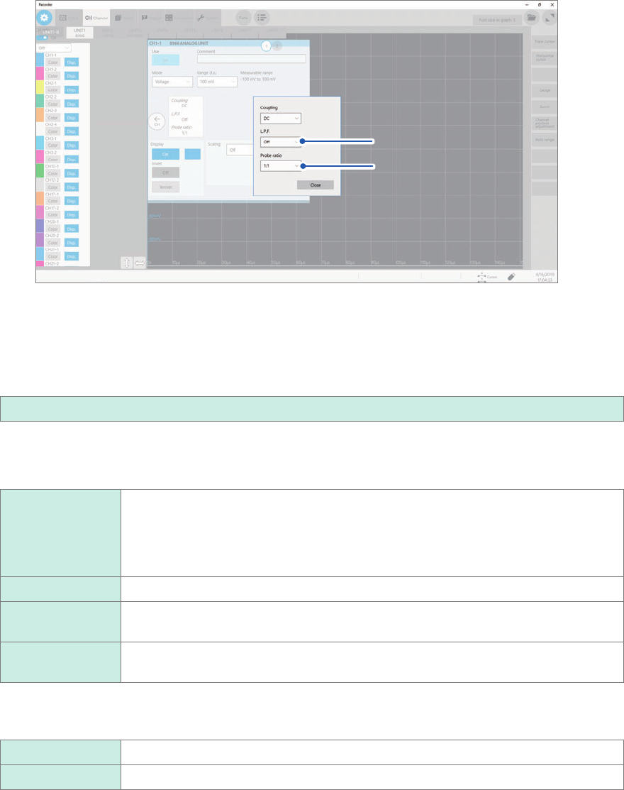
Select a cutoff frequency of the low-pass lter and a probe ratio in [L.P.F] and [Probe ratio],
respectively.
Click the area that includes [L.P.F] and [Probe ratio] allows the setting dialog box to appear.
(1)
(2)
(1) Click the [L.P.F] box, and then choose a cutoff frequency of the low-pass lter from the
list.
Enabling the low-pass lter in the module eliminates excessive harmonic components.
Available cutoff frequencies of the low-pass lter vary depending on the module type. Choose an adequate
cutoff frequency depending on the characteristics of an input signal.
Example: Model 8966 Analog Unit
Off
, 5 Hz, 50 Hz, 500 Hz, 5 kHz, 50 kHz, 500 kHz
(2) Click the [Probe ratio] box, and then choose a probe ratio from the list.
Congure this setting when you perform measurement using the instrument with connection cords or probes
connected.
1:1
Choose this option when using any of the following cords:
• Model L9197 Connection Cord
• Model L9790 Connection Cord
• Model L9198 Connection Cord (for low voltage)
• Model L9217 Connection Cord
1:10 Choose this ratio when using Model 9665 10:1 Probe.
1:100 Choose this ratio when using Model 9666 100:1 Probe, Model P9000-01 Differential
Probe, or Model P9000-02 Differential Probe.
1:1000 Choose this option when using Model 9322, Model P9000-01, or Model P9000-02
Differential Probe.
5
Click the [Display] button to set it to [On] or [Off].
On
Displays the waveform on the waveform screen.
Off Does not display any waveform.
6
When the [Display] button has been set to [On], click the box next to [On] on the right, and
choose a display color from the color pallet.
You can also choose the same color as lines acquired across other channels.
7
Switch the channels.
Switch the channels by clicking the corresponding point on the display.
73
Conguring the Level Trigger Settings
3.4 Conguring the Level Trigger Settings
The trigger function allows you to start and stop measurements using specic signals. When
recording is started by specic signals, it is called “The instrument is triggered.” The trigger function
is useful to nd trends in unexpected events. This section explains “level trigger,” which triggers
the instrument at a specied value. For details about triggers other than the level trigger, refer to “
5
Specifying the Trigger Settings”
of the Instruction Manual.
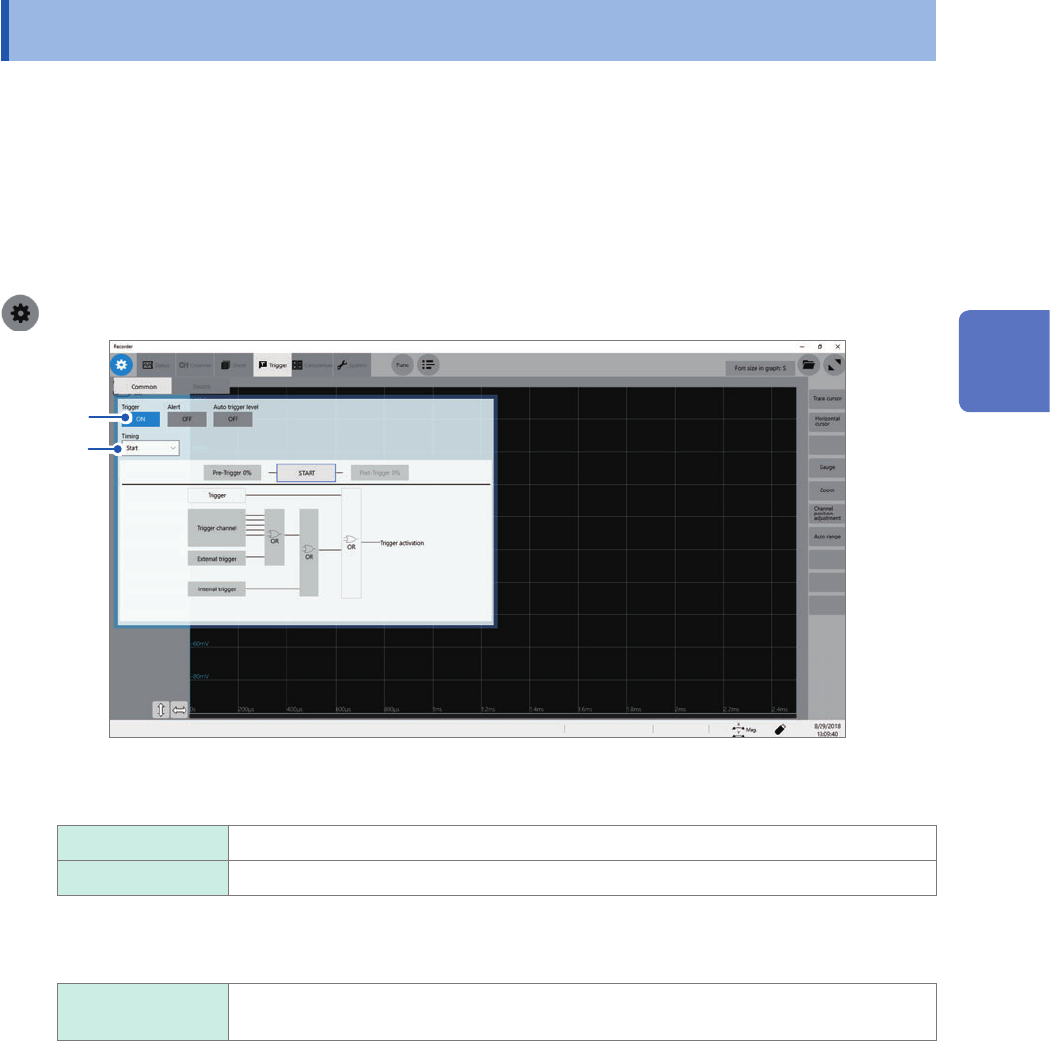
Cross-trigger settings
> [Trigger] > [Common]
2
1
1
Click the [Trigger] button to set it to [On] or [Off].
Off
Disables the trigger function.
On Enables the trigger function.
2
Click the [Timing] box, and then choose a trigger recording method from the list.
Start
Starts recording when the instrument is triggered, and stops the recording after the
instrument has acquired the recording-length waveforms.
3
Measurement Method
74
Conguring the Level Trigger Settings
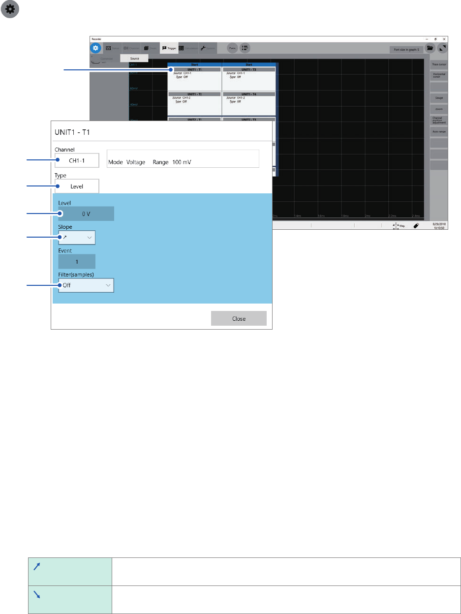
Conguring the trigger source settings
> [Trigger] > [Source]
1
3
2
4
5
6
1
Click a trigger source you want to specify.
The setting dialog box will appear.
You can set four triggers per module.
2
Click the [Channel] box, and then choose a channel to be used for the level trigger from the
list.
3
Click the [Type] box, and then choose [Level] from the list.
4
In the [Level] box, enter a threshold value the level trigger condition is satised at.
5
Click the [Slope] box, and then choose a signal direction that allows the level trigger
condition to be satised from the list.
Choose a direction used to trigger the instrument when the signal crosses the threshold value specied in
[Level].
The level-trigger condition is satised when a signal crosses the threshold value in the
positive direction.
The level-trigger condition is satised when a signal crosses the threshold value in the
negative direction.
6
Click the [Filter] box, and then choose a sampling count of the lter from the list.
Only after the level-trigger condition is continuously satised during the specied period, an analog trigger is
generated. This is useful to prevent the instrument from triggering due to noise.