MR8740T_Quick guide_eng_20191016H.pdf - 第53页
47 Attaching Connection Cords Connecting a charge-output acceleration sensor Connecting a charge-output acceleration sensor equipped with the miniature connector (#10-32) Model U8979 Charge Unit T ighten the screw . 1 Al…
46
Attaching Connection Cords
Acceleration sensor
Connect a acceleration sensor to Model U8979 Charge Unit
Familiarize yourself with “Operation Precautions” (p. 8) before connecting a current sensor.
Acceleration sensor connectable with Model U8979
CAUTION
Use an acceleration sensor with a built-in pre-amplier that conforms to the specication
of Model U8979 Charge Unit. Using an inapplicable sensor may cause damaging itself.
Acceleration sensor type Terminal the sensor is connected to Note
With a built-in pre-amplier BNC connector Drive power: 3.5 mA, 22 V
Charge output Miniature connector (#10-32) –
Connecting an acceleration sensor with a built-in pre-amplier
Connecting a BNC-output acceleration sensor with a built-in pre-amplier
U8979 Charge Unit
BNC connector slots
Locking studs of
module connector
Locking studs
1
Lock
2
1
Align the slots in the BNC connector of an
acceleration sensor with the locking studs of a
BNC connector on the module, and insert the
connector.
2
Turn the BNC connector of the acceleration
sensor clockwise until it locks.
3
Attach the acceleration sensor with the built-in
pre-amplier to a measuring object.
How to connect the cable and a sensor
Turn the BNC connector of the acceleration
sensor counter-clockwise to release the lock
and remove the connector.
Connecting an acceleration sensor other than a sensor with a built-in pre-amplier
Convert the output connector into the BNC connector using a commercially available conversion
connector or conversion cable to connect the sensor.
47
Attaching Connection Cords
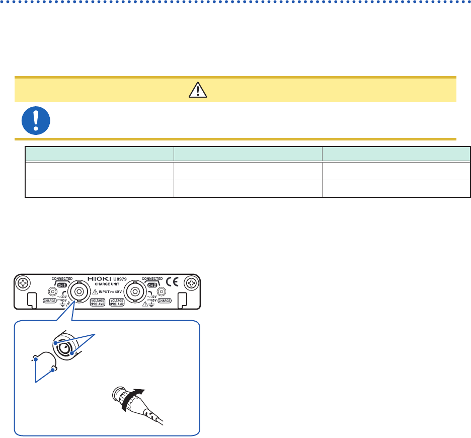
Connecting a charge-output acceleration sensor
Connecting a charge-output acceleration sensor equipped with the miniature connector
(#10-32)
Model U8979 Charge Unit
Tighten the
screw.
1
Align the screw of the miniature connector, and
turn the connector clockwise to tighten it.
2
Attach the charge-output acceleration sensor
to a measuring object.
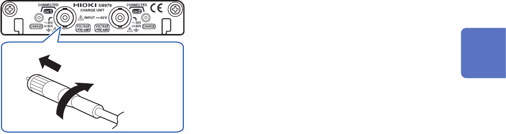
How to disconnect the current sensor
Turn the miniature connector counterclockwise,
and then pull out the connector.
Connecting an charge-output acceleration sensor equipped with a connector other than a
miniature connector (#10-32)
Convert the output connector into the miniature connector (#10-32) using a commercially available
conversion connector or conversion cable to connect the sensor.
2
Preparing for Measurement
48
Attaching Connection Cords
Logic probe (Measuring logic signals)
Connect logic probes to Model 8973 Logic Unit.
Refer to “Before connecting a logic probe to a measuring object” (p. 17).
Refer to an instruction manual of each logic probe.
Required item: Logic probe (Model 9320-01, Model MR9321-01, or Model 9327)
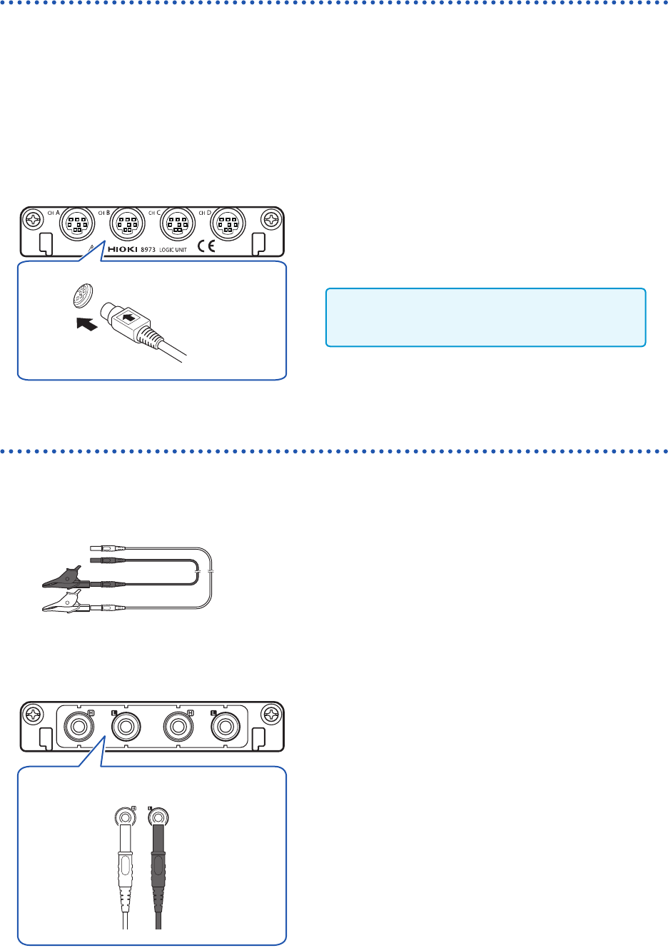
How to connect a logic probe
Example: Connecting Model 9327 Logic Probe
Model 8973 Logic Unit
1
Align the plug slots of the logic probe with a
logic terminal, and insert the logic-probe plug.
2
Connect the logic probe to a measuring object.
Only slots to which UNIT 25, UNIT 26, or UNIT
27 is assigned are available.
Connection cable (For precisely measuring voltage)
Connect Model L2200 Test Lead to a module.
Required item: Model L2200 Test Lead (maximum input voltage: 1000 V)
How to connect a logic probe
Model MR8990 Digital Voltmeter Unit
H L
Red Black
1
Connect the test leads to the banana jacks on
the module.
Connect the black lead to the L jack; and the red lead to
the H jack. Make sure the test leads are fully inserted into
the jacks.
2
Connect the test leads to a measuring object.