MR8740T_Quick guide_eng_20191016H.pdf - 第61页
55 Connecting the Instrument with computers 2.4 Connecting the Instrument with computers Connecting the instruments with computers via a LAN cable allows computers to control and monitor the instrument. Connect LAN cable…
54
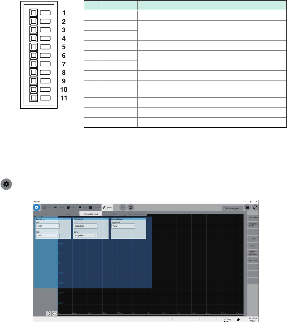
Connecting the External Control Terminals
Terminal block
No. Pin name Operation
1 GND –
2 IN1
Starts/stops measurement, saves data les, aborts
measurement, enters events
3 IN2
4 GND –
5 OUT1
Outputs signals indicating judgments and status (error,
busy, waiting for a trigger)
6 OUT2
7 GND –
8 EXT.TRIG
The instrument is triggered when an external signal is
inputted as a trigger source.
9 TRIG.OUT Outputs a signal when the instrument is triggered.
10 GND –
11 EXT.SMPL Input a external sampling signal.
How to congure the external control terminal settings
On the [External terminal] screen, you can congure the following terminal: the external input (IN1,
IN2), external output (OUT1, OUT2), and trigger output (TRIG.OUT). Use the [Trigger] screen to
congure the external trigger (EXT.TRIG) setting.
> [System] > [External terminal]
55
Connecting the Instrument with computers
2.4 Connecting the Instrument with computers
Connecting the instruments with computers via a LAN cable allows computers to control and
monitor the instrument. Connect LAN cables to the 1000BASE-T connector of computers and
instrument. The procedures for connecting the cables (2 ways) are as follows.
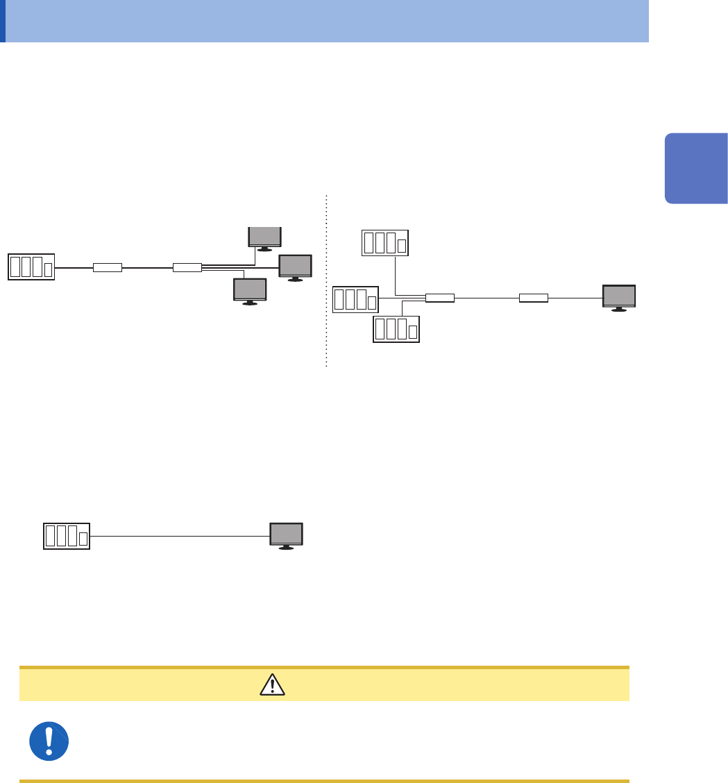
(1) Connecting the instrument to the existing network
Connecting the instruments with a hub via LAN cables allows computers to control and monitor the
instruments.
Connecting one instrument to multiple PCs Connecting multiple instruments to one computer
LAN cable* LAN cable*
Hub Hub
Model MR8740T
LAN
Computer
LAN
HubHub
Model MR8740T
LAN cable*
LAN cable*
Computer
*: Use one of the following cables:
• 1000BASE-T straight-through cable (maximum length: 100 m, commercially available)
• Model 9642 LAN Cable (optional)
(2) One-to-one connection of the instrument and a computer
Connecting the instruments with computers via a LAN cable allows computers to control and
monitor the instrument.
Model MR8740T
Computer
LAN cable*
*: Use one of the following cables:
• 1000BASE-T compatible crossover cable (maximum length: 100 m)
• 1000BASE-T straight-through cable and crossover connector (maximum length: 100 m)
• Model 9642 LAN Cable (optional, coming with crossover connector)
CAUTION
When connecting the instrument to your LAN using a LAN cable of more than 30 m or
with a cable laid outdoors, take appropriate countermeasures that include installing a
surge protector for LANs. Such signal wiring is susceptible to induced lighting, which
can cause damage to the instrument.
2
Preparing for Measurement
56
Connecting the Instrument with computers
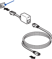
When connecting the instrument and the computer using Model 9642 LAN Cable and the
accompanying crossover connector
Model 9642 LAN Cable
Crossover connector
1000BASE-T connector of instrument
Connect it to your computer.
1
2
3
1
Connect Model 9642 LAN Cable to the
accompanying crossover connector.
2
Connect the crossover connector to the
1000BASE-T connector of the instrument.
3
Connect Model 9642 LAN Cable to the
1000BASE-T connector of your computer.