MR8740T_Quick guide_eng_20191016H.pdf - 第55页
49 Attaching Connection Cords Outputting waveforms Connect the connection cable to an SMB terminal of Model MR8790. Required item: Model L9795-01/L9795-02 Connection Cable • Model L9795-01 Connection Cable (mini-alligato…
48
Attaching Connection Cords
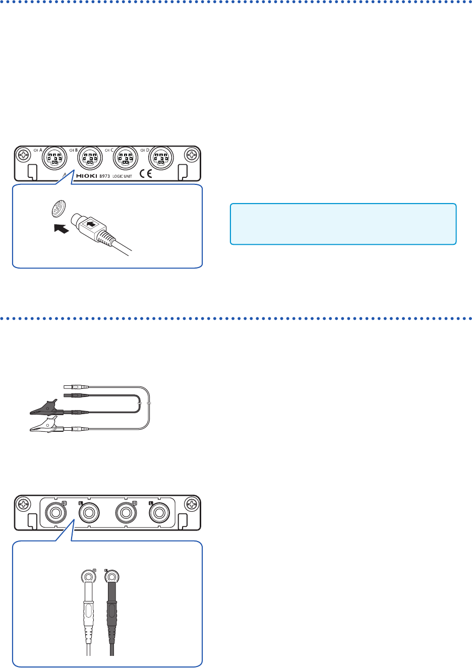
Logic probe (Measuring logic signals)
Connect logic probes to Model 8973 Logic Unit.
Refer to “Before connecting a logic probe to a measuring object” (p. 17).
Refer to an instruction manual of each logic probe.
Required item: Logic probe (Model 9320-01, Model MR9321-01, or Model 9327)
How to connect a logic probe
Example: Connecting Model 9327 Logic Probe
Model 8973 Logic Unit
1
Align the plug slots of the logic probe with a
logic terminal, and insert the logic-probe plug.
2
Connect the logic probe to a measuring object.
Only slots to which UNIT 25, UNIT 26, or UNIT
27 is assigned are available.
Connection cable (For precisely measuring voltage)
Connect Model L2200 Test Lead to a module.
Required item: Model L2200 Test Lead (maximum input voltage: 1000 V)
How to connect a logic probe
Model MR8990 Digital Voltmeter Unit
H L
Red Black
1
Connect the test leads to the banana jacks on
the module.
Connect the black lead to the L jack; and the red lead to
the H jack. Make sure the test leads are fully inserted into
the jacks.
2
Connect the test leads to a measuring object.
49
Attaching Connection Cords
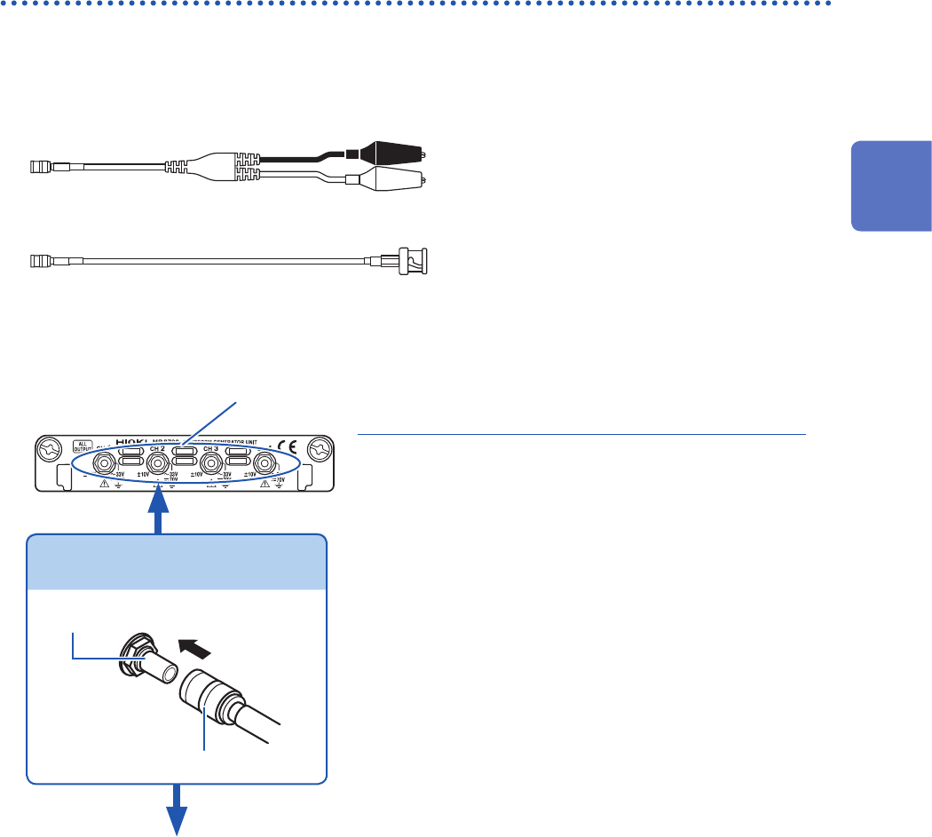
Outputting waveforms
Connect the connection cable to an SMB terminal of Model MR8790.
Required item: Model L9795-01/L9795-02 Connection Cable
• Model L9795-01 Connection Cable (mini-alligator clip type)
• Model L9795-02 Connection Cable (BNC output type)
How to connect the cable to an output terminal
Example: Model MR8790 Waveform Generator Unit
Output terminal
SMB connector
Attach the connection cable.
2
Attach the connection cable to a target.
Output
terminal
1
Insert the SMB connector of the connection
cable to an output terminal until the connector
clicks.
3
Attach the clips of the connection cable to a
target.
How to disconnect the cable from the output
terminal
Hold the head of the SMB connector (other than the
cable) and pull it out.
1
2
Preparing for Measurement
50
Attaching Connection Cords
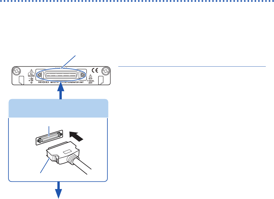
Outputting pulse waveforms
Connect the connection cable to Model MR8791 Pulse Generator Unit.
Required item: Commercially available cable (Half-pitch 50 pins)
How to connect the cable to the output connector
1
Output connector
2
Attach the connection cable to a target.
1
Attach the connector of the connection cable
to an output connector of the module.
4
Attach the connection cable to a target.
How to disconnect the cable from the output
terminal
While holding down the buttons, pull our the connector.
Connector of connection cable
Buttons
Output connector
Connecting the connection cable
Output connector
10250-52A2PL: 3M (SCSI-2 connector, Centronics half-pitch, 50 pins, female)
Refer to “Model MR8791 Pulse Generator Unit” (p. 134).
• The metal shell of the 10250-52A2PL connector is equipotential to the chassis ground (frame ground).
• Use a lock-type connector to attach a harness to the connector of the module.