MR8740T_Quick guide_eng_20191016H.pdf - 第28页
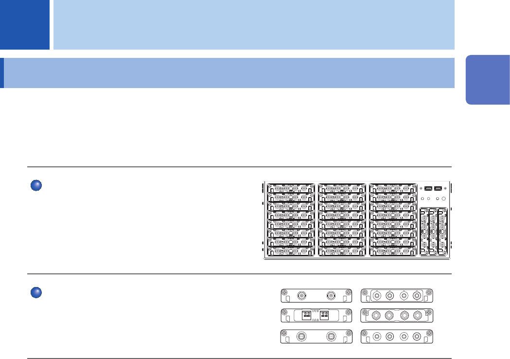
22 Name and Function of Each Part 1.2 Name and Function of Each Part Front side 1 2 3 4 5 6 No. Name Function Reference page 1 Module embedding part Up to 27 modules can be installed in the instrument. Y ou can install a…
21
1
Overview
1.1 Product Overview and Features
This recorder allows you to observe a wide range of waveforms from low-speed signals to high-
speed waveforms.
You can mainly use this instrument for analyzing test and evaluation results of various products and
troubleshooting those products.
Multichannel simultaneous sampling
This instrument can simultaneously measure signals
across up to 108 channels.
Extensive line of measurement modules
Many types of measurement modules let the
instrument measure a variety of signals that include
voltage, current, temperature, and frequency.
1 Overview
1
Overview
22
Name and Function of Each Part
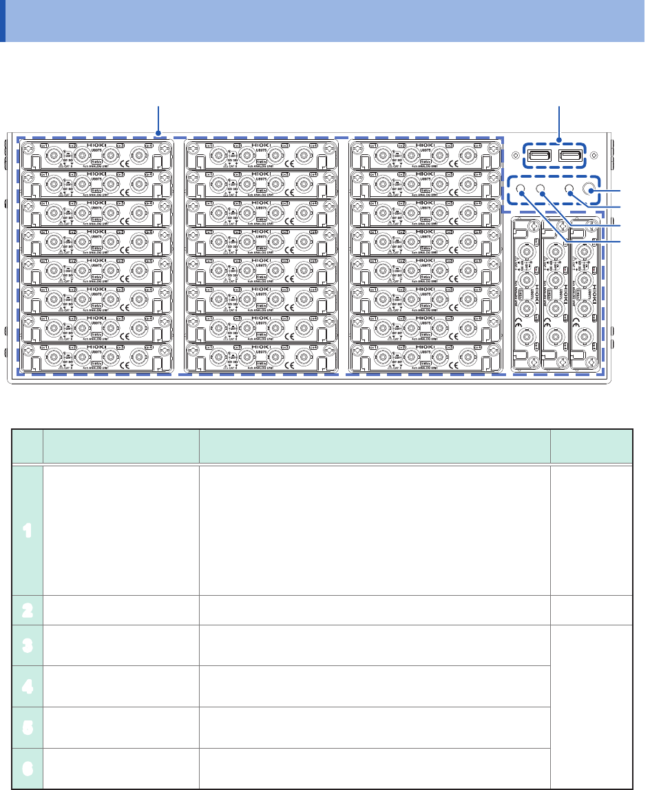
1.2 Name and Function of Each Part
Front side
1
2
3
4
5
6
No. Name Function
Reference
page
1
Module embedding part
Up to 27 modules can be installed in the instrument.
You can install as many modules of Model 8971 Current
Unit and Model U8977 3CH Current Unit as possible in any
slots unless the total number of connectable current sensors
reaches nine. Model 8973 Logic Unit can be installed in slots
to which UNIT 25, UNIT 26, or UNIT 27 is assigned only.
Refer to an instruction manual that comes with each input
module.
p. 10
p. 34
2
USB2.0 connector Connect a USB ash drive, USB mouse, or USB keyboard. p. 57
3
Start button. Activates the instrument or puts it into standby when pressed.
p. 24
4
POWER lamp
Indicates whether the instrument is powered on or in standby
mode.
5
DIAG lamp Indicates instrument status.
6
Command error lamp Lights up if a command error occurs.
23
Name and Function of Each Part
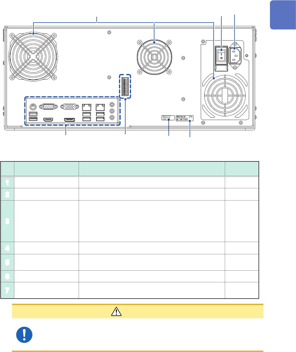
Rear side
1
3
4
2
5
6
7
No. Name Function
Reference
page
1
Vents (fan motors) Do not block the vents. –
2
Windows
®
license The Windows
®
license label is afxed. –
3
Serial number
Used to identify the instrument. The serial number consists
of nine digits. The rst two (from the left) indicate the year
of manufacture, and the next two indicate the month of
manufacture. Do not remove this label.
Inform your authorized Hioki distributor or reseller of this
number if required.
–
4
Main power switch Turns the instrument on and off. –
5
Power inlet Connects the power cord provided.
p. 18
p. 60
6
Interface terminals Connect an LCD, LAN cable, and USB cable. p. 25
7
External control
terminals
Connect an external device. p. 53
CAUTION
If you set the main power switch to off while the instrument is powered on, the power
from the built-in battery is lost, resulting in incorrect Windows
®
shutdown. Be sure to use
the front start button to set the instrument in the standby state, and then set the main
power switch to off.
1
Overview