MR8740T_Quick guide_eng_20191016H.pdf - 第51页
45 Attaching Connection Cords By using Model CT9920 Conversion Cable (optional), you can connect a current sensor of Model CT7000 series with Model U8977 3CH Current Unit. The instrument cannot recognize any sensor with …
44
Attaching Connection Cords
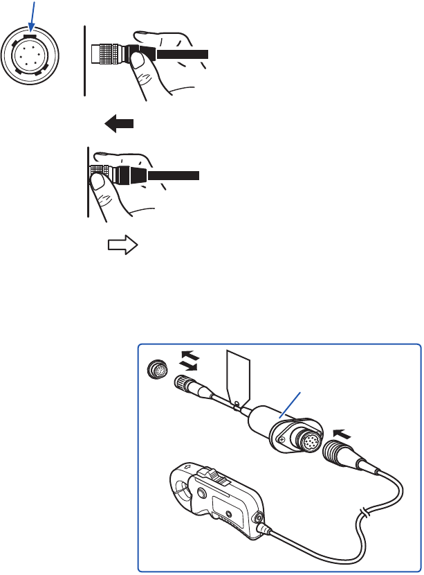
Connecting a current sensor with Model U8977 3CH Current Unit
You can directly connect a current sensor with the sub model-number “-05,” which has a metal
connector (ME15W).
Hold the metal
sleeve.
Point the widest key upward.
1
Align the connector guides of the cable with
those of the module connector.
2
Straightly insert the connector until it locks.
Hold the part other than metal to insert the
connector.
The instrument automatically recognizes the
model of the current sensor.
How to disconnect the current sensor
1
Hold and pull the metal collar, which releases
the lock.
2
Pull the connector.
Using Model CT9900 Conversion Cable, you can connect a current sensor without the sub model-
number “-05,” which has a plastic connector (PL23), with Model U8977 3CH Current Unit.
Model CT9900
Conversion Cable
When Model CT9900 Conversion Cable is used, the instrument recognizes Model CT6846 or
CT6865 (1000 A rating) as a 500-A AC/DC sensor. Set the conversion ratio to 2.00.
45
Attaching Connection Cords
By using Model CT9920 Conversion Cable (optional), you can connect a current sensor of Model
CT7000 series with Model U8977 3CH Current Unit. The instrument cannot recognize any sensor
with Model CT9920 connected.
Select a mode in the setting screen.
Supported models Model CT7631, Model CT7636, Model CT7642, Model CT7731, Model CT7736,
Model CT7742, Model CT7044, Model CT7045,
Model CT7046
Model CT9920
Conversion Cable
For current sensor
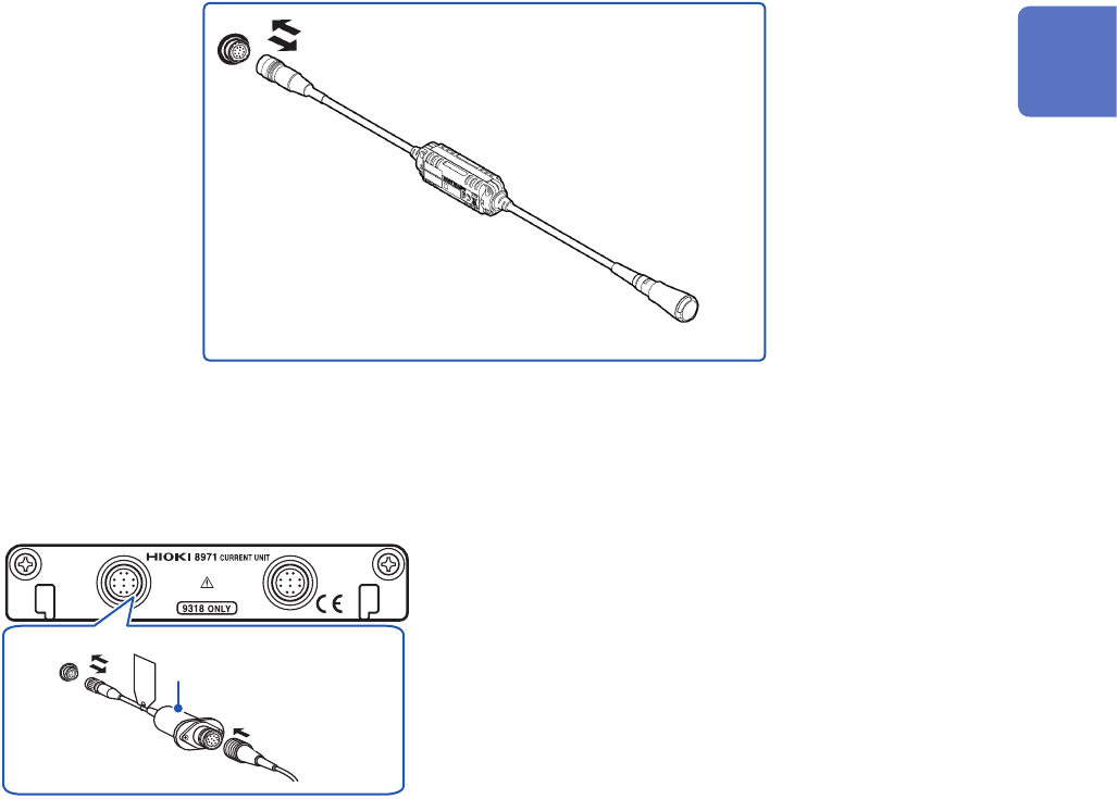
Connecting a current sensor with Model 8971 Current Unit
By using Model 9318 Conversion Cable*, you can connect a current sensor without the sub model-
number “-05,” which has a plastic connector (PL23), with Model 8971 Current Unit..
*: Model 9318 Conversion Cable is an accessory of Model 8971 Current Unit.
Model 9318
Conversion Cable
1
2
Model 8971 Current Unit
1
Align the guides of the conversion cable with
those of the sensor connector on the module,
and straightly insert the plug until it locks.
2
Align the guides of the current sensor to
be used with those of the conversion cable
connector, and straightly insert the plug until it
locks.
The instrument automatically recognizes the
model of the current sensor.
3
Clamp the current sensor around a line of a
measuring object.
How to connect the cable and a sensor
1
Hold and pull the plastic collar of the
conversion cable, which releases the lock, and
the remove the connector.
2
Hold and pull the plastic collar of the current
sensor, which releases the lock, and the
remove the connector.
When measuring currents with a voltage module
Using Model 9018-50 Clamp on Probe, you can measure a current using a voltage measurement
module such as Model 8966 Analog Unit.
Conguring the scaling settings allows measured waveforms to be displayed as current values. For
the setup procedure, refer to “Converting Input Values (Scaling Function)” of the Instruction Manual.
2
Preparing for Measurement
46
Attaching Connection Cords
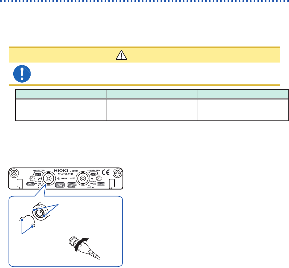
Acceleration sensor
Connect a acceleration sensor to Model U8979 Charge Unit
Familiarize yourself with “Operation Precautions” (p. 8) before connecting a current sensor.
Acceleration sensor connectable with Model U8979
CAUTION
Use an acceleration sensor with a built-in pre-amplier that conforms to the specication
of Model U8979 Charge Unit. Using an inapplicable sensor may cause damaging itself.
Acceleration sensor type Terminal the sensor is connected to Note
With a built-in pre-amplier BNC connector Drive power: 3.5 mA, 22 V
Charge output Miniature connector (#10-32) –
Connecting an acceleration sensor with a built-in pre-amplier
Connecting a BNC-output acceleration sensor with a built-in pre-amplier
U8979 Charge Unit
BNC connector slots
Locking studs of
module connector
Locking studs
1
Lock
2
1
Align the slots in the BNC connector of an
acceleration sensor with the locking studs of a
BNC connector on the module, and insert the
connector.
2
Turn the BNC connector of the acceleration
sensor clockwise until it locks.
3
Attach the acceleration sensor with the built-in
pre-amplier to a measuring object.
How to connect the cable and a sensor
Turn the BNC connector of the acceleration
sensor counter-clockwise to release the lock
and remove the connector.
Connecting an acceleration sensor other than a sensor with a built-in pre-amplier
Convert the output connector into the BNC connector using a commercially available conversion
connector or conversion cable to connect the sensor.