MR8740T_Quick guide_eng_20191016H.pdf - 第57页
51 Attaching Connection Cords Outputting voltage, current, and resistance Attach the connection cable to Model U8794 VIR Generator Unit . Required item: commercially available cable (D-sub 25 pins) How to connect the cab…
50
Attaching Connection Cords
Outputting pulse waveforms
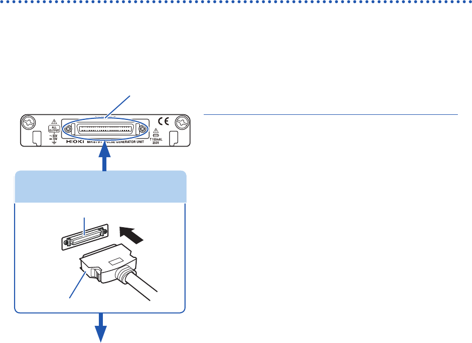
Connect the connection cable to Model MR8791 Pulse Generator Unit.
Required item: Commercially available cable (Half-pitch 50 pins)
How to connect the cable to the output connector
1
Output connector
2
Attach the connection cable to a target.
1
Attach the connector of the connection cable
to an output connector of the module.
4
Attach the connection cable to a target.
How to disconnect the cable from the output
terminal
While holding down the buttons, pull our the connector.
Connector of connection cable
Buttons
Output connector
Connecting the connection cable
Output connector
10250-52A2PL: 3M (SCSI-2 connector, Centronics half-pitch, 50 pins, female)
Refer to “Model MR8791 Pulse Generator Unit” (p. 134).
• The metal shell of the 10250-52A2PL connector is equipotential to the chassis ground (frame ground).
• Use a lock-type connector to attach a harness to the connector of the module.
51
Attaching Connection Cords
Outputting voltage, current, and resistance
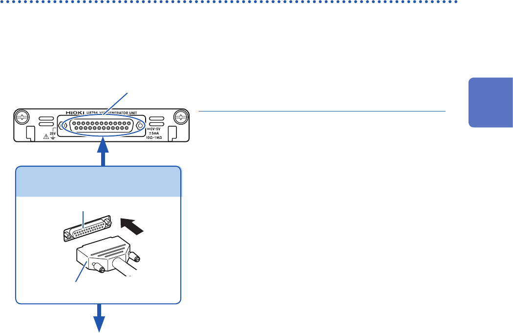
Attach the connection cable to
Model U8794 VIR Generator Unit
.
Required item: commercially available cable (D-sub 25 pins)
How to connect the cable to the output connector
1
Output connector
2
Attach the connection cable to a target.
1
Attach the connector of the connection cable
to the output connector of the module and
tighten the screws.
2
Attach the connection cable to a target.
How to disconnect the cable from the output
terminal
Loosen the screws of the output terminals.
Connector of connection cable
Buttons
Output connector
Connecting the connection cable
Output connector
09663527617, Harting (D-sub 25 pins, female)
Refer to “Specications of the output connector” (p. 136).
The metal shell of the 09663527617 connector is equipotential to the chassis ground (frame ground).
2
Preparing for Measurement
52
Attaching Connection Cords
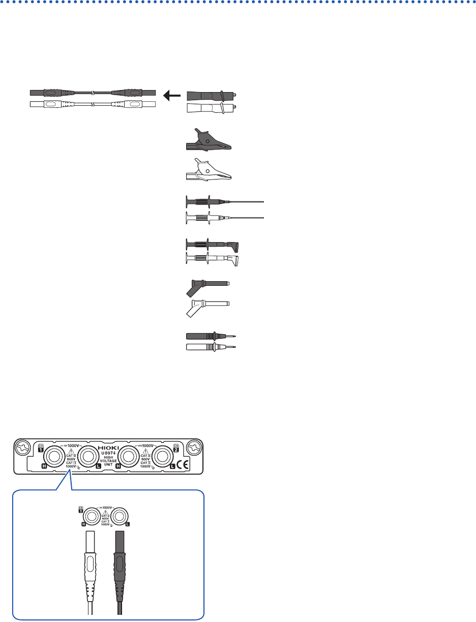
Connection cable (high voltage)
Connect Model L4940 Connection Cable Set to Model U8974 High Voltage Unit. Choose
appropriate connection cord tips based on the maximum input voltage and terminal type.
Required item: Model L4940 Connection Cable Set
Model L4934* Small
Alligator Clip Set
CAT III 300 V
CAT II 600 V
Model L4935 Alligator Clip
Set
CAT III 1000 V
CAT IV 600 V
Model 9243 Grabber Clip CAT III 1000 V
Model L4936 Bus Bar Clip
Set
CAT III 600 V
Model L4937 Magnetic
Adapter Set
CAT III 1000 V
Model L4932 Test Pin Set CAT III 1000 V
CAT IV 600 V
* Using Model L4934 requires Model L4932.
How to connect the thermocouple
Model U8974 High Voltage Unit
Red Black
H L
1
Connect the plugs of the connection cord to
the banana jacks on the module.
Connect the plugs to the banana jacks of their respective
colors.
2
Insert the accessory clips into the clip ends of
the connection cord.
3
Connect the connection cord clips to a
measuring object.