MR8740T_Quick guide_eng_20191016H.pdf - 第41页
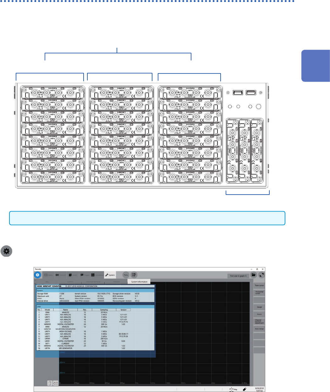
35 Installing and Removing Modules Allocation of modules and channels Module numbers Channel numbers The channels are numbered beginning from the top left. Units 25 through 27 (L to R) Units 1 through 8 Units 9 through 1…
34
Installing and Removing Modules
2.1 Installing and Removing Modules
If you order the instrument with modules specied, the instrument will be delivered with the modules
pre-installed. Follow the procedures below to install a module additionally, replace modules, or
remove a module. Up to four modules of Model 8971 Current Unit and up to three modules of
Model 8973 Logic Unit can be installed to the instrument.
Refer to “Handling the instrument and modules” (p. 10).
Required items: Phillips-head screwdriver (No. 2)
How to install a module
Right side
1
Orient and insert the module all the way into the
instrument.
2
Tighten the two screws with the Phillips-head
screwdriver to secure the module.
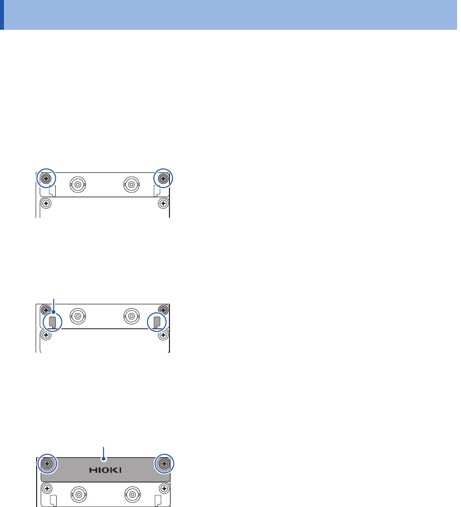
How to remove the module
Knob
1
Loosen the two module mounting screws with the
Phillips-head screwdriver.
2
Pinch the two knobs and pull out the module.
When not installing any module after removal
Install a blank panel. To order additional blank panels, contact your authorized Hioki distributor or
reseller.
Blank panel
1
Place a blank panel.
2
Tighten the two screws with the Phillips screwdriver
to secure the blank panel.
35
Installing and Removing Modules
Allocation of modules and channels
Module numbers
Channel numbers
The channels are numbered
beginning from the top left.
Units 25 through 27 (L to R)
Units 1 through 8
Units 9 through 16 Units 17 through 24
Modules are numbered beginning at the top.
Model 8973 Logic Unit can be installed in slots to which Unit 25, 26, or 27 is assigned only.
You can nd out information about the modules installed in the instrument in [System information].
Refer to “System conguration check” (p. 158).
> [System] > [System information]
2
Preparing for Measurement
36
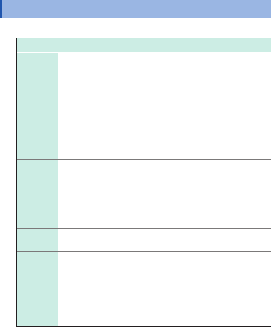
Attaching Connection Cords
2.2 Attaching Connection Cords
Refer to the manuals of the modules and connection cables if provided.
Measurement Applicable module Cable to be connected
Reference
page
Voltage
Model 8966 Analog Unit
Model 8968 High Resolution Unit
Model 8972 DC/RMS Unit
Model U8975 4ch Analog Unit
Model U8978 4CH Analog Unit
Model U8979 Charge Unit*
Model L9197 Connection Cord
Model L9198 Connection Cord
(For measuring low-voltage)
Model L9217 Connection Cord
Model L9790 Connection Cord
Model 9665 10:1 Probe
Model 9666 100:1 Probe
Model 9322 Differential Probe
Model P9000-01 Differential Probe
Model P9000-02 Differential Probe
Model 9166 Connection Cord*
(For inputting voltage
into Model U8979)
p. 17
p. 38
Frequency
Rotation
speed
Count
Model 8970 Freq Unit
Temperature Model 8967 Temp Unit Thermocouple p. 40
Vibration
Load
Pressure
Acceleration
Torque
Displacement
Model U8969 Strain Unit Strain gauge transducer p. 41
U8979 Charge Unit Acceleration sensor p. 46
Current
Model 8971 Current Unit
Model U8977 3CH Current Unit
(Up to nine current sensors)
Current sensor p. 43
Logic signal
Model 8973 Logic Unit
(Up to 3 modules)
Model 9320-01 Logic Probe
Model MR9321-01 Logic Probe
Model 9327 Logic Probe
p. 48
Voltage
(precision)
Model MR8990 Digital Voltmeter Unit Model L2200 Test Lead p. 48
Model U8991 Digital Voltmeter Unit
Model L9197 Connection Cord
Model L9198 Connection Cord
(for measuring low-voltage)
Model L9217 Connection Cord
Model L9790 Connection Cord
p. 38
High voltage Model U8974 High Voltage Unit
Model L4940 Connection Cable
Set
p. 52
*: Model 9166 Connection Cord can be used for Model U8979 Charge Unit only.