MR8740T_Quick guide_eng_20191016H.pdf - 第29页
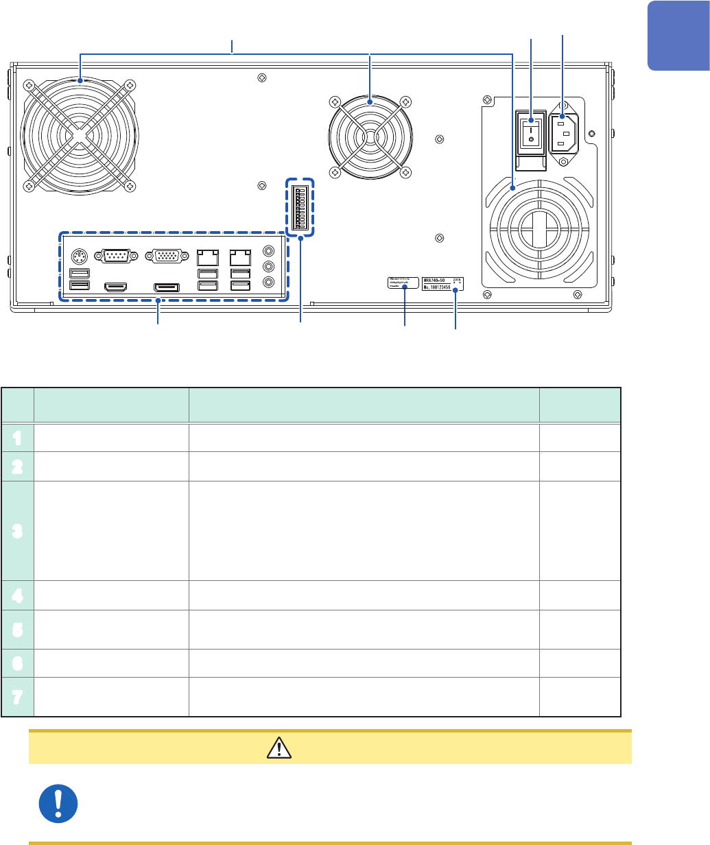
23 Name and Function of Each Part Rear side 1 3 4 2 5 6 7 No. Name Function Reference page 1 V ents (fan motors) Do not block the vents. – 2 Windows ® license The Windows ® license label is afxed. – 3 Serial number Used…
22
Name and Function of Each Part
1.2 Name and Function of Each Part
Front side
1
2
3
4
5
6
No. Name Function
Reference
page
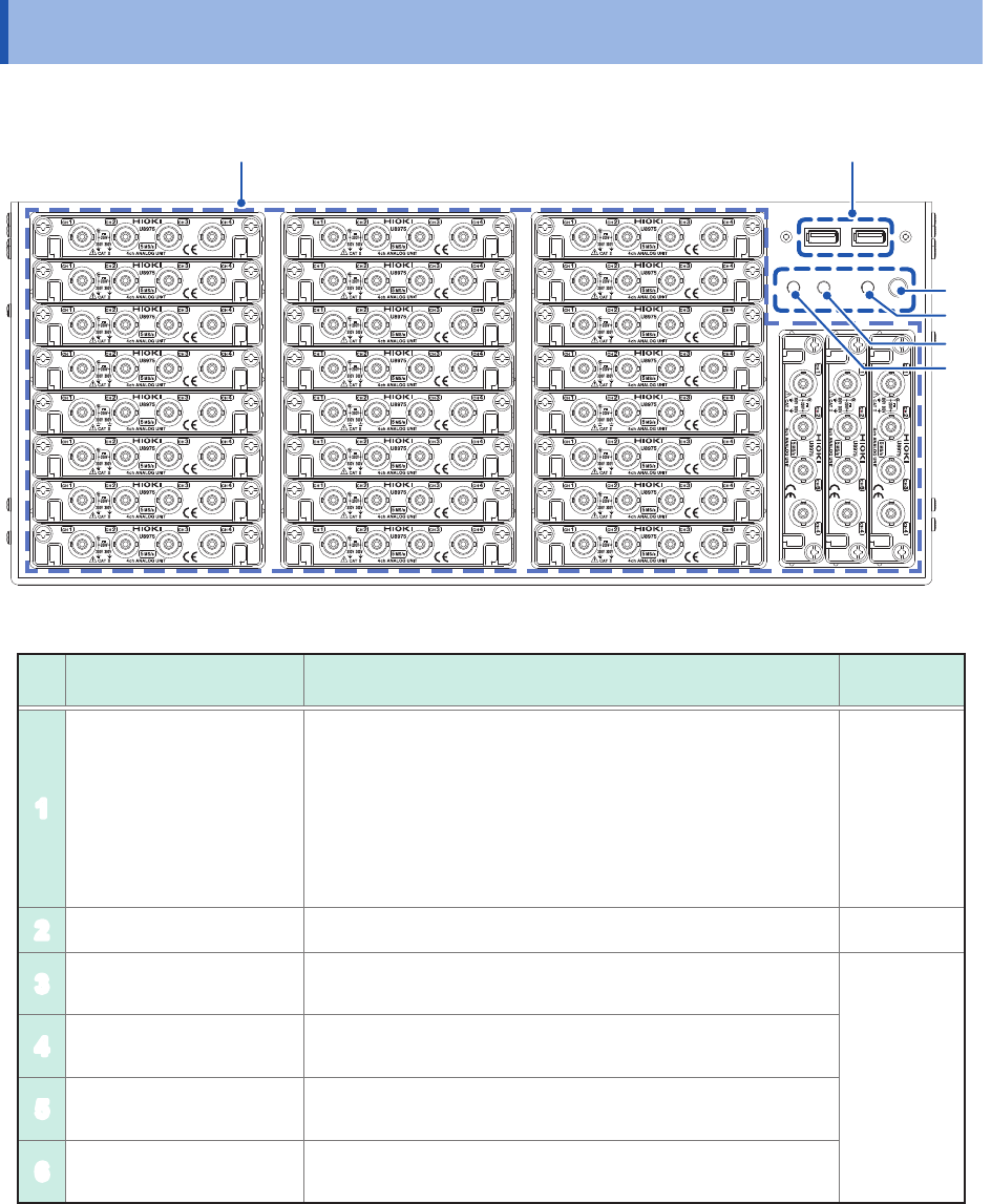
1
Module embedding part
Up to 27 modules can be installed in the instrument.
You can install as many modules of Model 8971 Current
Unit and Model U8977 3CH Current Unit as possible in any
slots unless the total number of connectable current sensors
reaches nine. Model 8973 Logic Unit can be installed in slots
to which UNIT 25, UNIT 26, or UNIT 27 is assigned only.
Refer to an instruction manual that comes with each input
module.
p. 10
p. 34
2
USB2.0 connector Connect a USB ash drive, USB mouse, or USB keyboard. p. 57
3
Start button. Activates the instrument or puts it into standby when pressed.
p. 24
4
POWER lamp
Indicates whether the instrument is powered on or in standby
mode.
5
DIAG lamp Indicates instrument status.
6
Command error lamp Lights up if a command error occurs.
23
Name and Function of Each Part
Rear side
1
3
4
2
5
6
7
No. Name Function
Reference
page
1
Vents (fan motors) Do not block the vents. –
2
Windows
®
license The Windows
®
license label is afxed. –
3
Serial number
Used to identify the instrument. The serial number consists
of nine digits. The rst two (from the left) indicate the year
of manufacture, and the next two indicate the month of
manufacture. Do not remove this label.
Inform your authorized Hioki distributor or reseller of this
number if required.
–
4
Main power switch Turns the instrument on and off. –
5
Power inlet Connects the power cord provided.
p. 18
p. 60
6
Interface terminals Connect an LCD, LAN cable, and USB cable. p. 25
7
External control
terminals
Connect an external device. p. 53
CAUTION
If you set the main power switch to off while the instrument is powered on, the power
from the built-in battery is lost, resulting in incorrect Windows
®
shutdown. Be sure to use
the front start button to set the instrument in the standby state, and then set the main
power switch to off.
1
Overview
24
Name and Function of Each Part
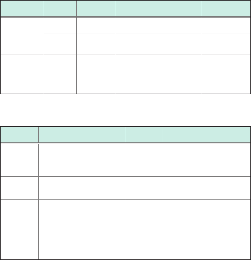
Instrument status indicator
The LEDs indicate the instrument status.
Basic LED indicator
LED name Color Lighting up /
blinking
When lights up How to turn off
the LED
POWER
STANDBY
Orange Lighting up Stand-by status Set the rear switch
to off.
Green Lighting up Power-on status Shut the power off.
Green Blinking Power-on status (warm-up) Shut the power off.
DIAG Refer to the
table below.
Refer to the
table below.
Refer to the table below.
–
CMD ERR Red Lighting up A command received contained a
syntax error.
Send the
*CLS
command to turn
off the LED.
Details of DIAG LED
DIAG LED mode table
Indicator
priority order
Status Color Note
1 The inside temperature is high
(ambient temperature > 35°C).
Red
–
2 The inside temperature is low
(ambient temperature < 10°C).
Purple
–
3 CPU load rate ≥ 80% Yellow Updated every 0.5 seconds, based
on average load rates calculated
over the period.
4 Waiting for a trigger. Blue –
4 The recording is in progress. Green –
4 The recording is complete. Pink Switches to the normal operation
indication when a new command is
received.
5 During normal operation (under
suspension)
White
–