MR8740T_Quick guide_eng_20191016H.pdf - 第44页
38 Attaching Connection Cords Connection cables (For measuring voltage, frequency , or rotation speed, and obtaining accumulations) Insert connection cords to modules. Choose an appropriate connection cord based on the m…
37
Attaching Connection Cords
Output Applicable module Cable to be connected
Reference
page
Waveform Model MR8790 Waveform Generator Unit
Model L9795-01 Connection
Cable
Model L9795-02 Connection
Cable
p. 49
Pulse Model MR8791 Pulse Generator Unit
Commercially available cable
(Half-pitch 50 pins)
p. 50
DC voltage
DC current
Resistance
(simulated)
Model U8794 VIR Generator Unit
Commercially available cable
(D-sub 25 pins)
p. 51
2
Preparing for Measurement
38
Attaching Connection Cords
Connection cables (For measuring voltage, frequency, or rotation
speed, and obtaining accumulations)
Insert connection cords to modules. Choose an appropriate connection cord based on the
maximum input voltage and tips of cables.
The maximum input voltage of the instrument or connection cord, whichever is lower, is applicable.
Refer to “Before connecting cords” (p. 16).
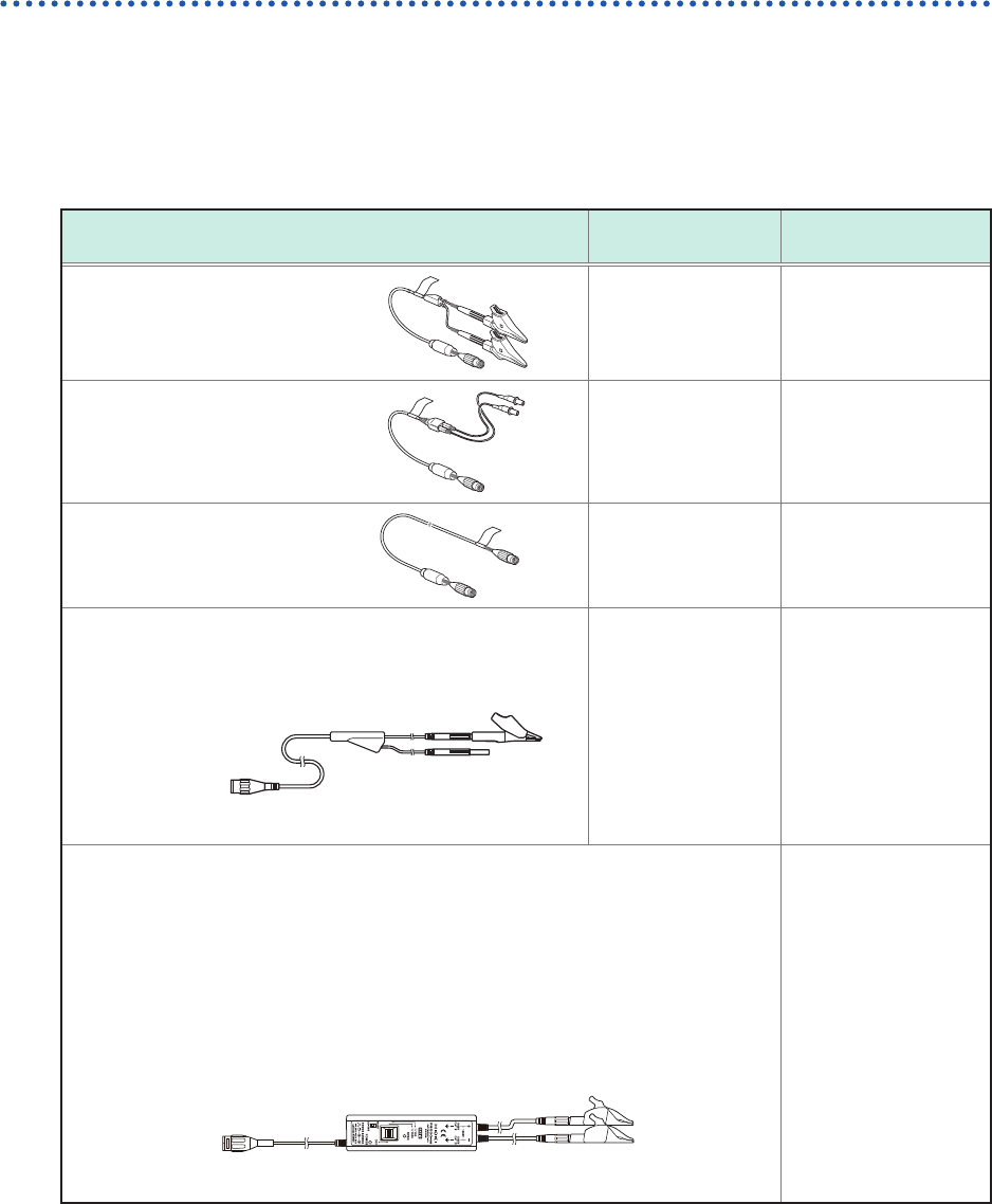
Required items: Connection cords
Connection cord
Maximum input
voltage
Type
Model L9197
Connection Cord
600 V Large alligator clip
Model L9198
Connection Cord
300 V Small alligator clip
Model L9217
Connection Cord
300 V BNC output
Model L9790 Connection Cord
Example: with the alligator clip attached.
600 V Alligator clip
Grabber clip
Contact pin
When the voltage to be measured exceeds the maximum input rating of the module
being used
(excluding Model U8991 Digital Voltmeter Unit)
Model 9665 10:1 Probe*
1
Model 9666 100:1 Probe*
1
Model 9322 Differential Probe*
2
Model P9000-01 Differential Probe*
3
Model P9000-02 Differential Probe*
3
Example: Model P9000-02 Differential Probe
Alligator clip
*1: The maximum rated voltage to earth depends on a module to be used.
*2: An optional power cord or AC adapter is required.
*3: An optional AC adapter or a commercially available USB cable is required.
39
Attaching Connection Cords
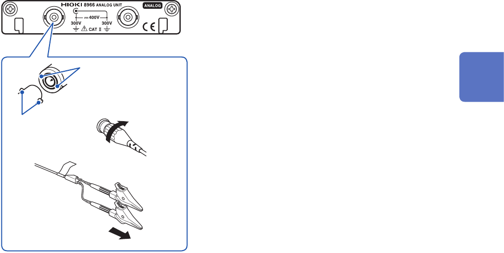
How to connect a cord
Example: Model 8966 Analog Unit
BNC connector slots
Locking studs of
module connector
Locking studs
1
Lock
2
3
1
Align the slots in the BNC connector of a
connection cord with the locking studs of a
BNC connector on the module, and insert the
connector.
2
Turn the BNC connector of the connection cord
clockwise until it locks.
3
Connect the connection cord clips to a
measuring object.
How to disconnect the cord
Turn the BNC male connector of the connection cable
counterclockwise, and then pull out the connector.
2
Preparing for Measurement