MR8740T_user_manual_eng_20191016H.pdf - 第114页
109 T riggering the Instrument Using Analog Signals (Analog T rigger) 2. [In] trigger, [Out] trigger When an input signal falls within ( [In] ) or gets out of a range ( [Out] ), which is determined by specifying upper an…

108
Triggering the Instrument Using Analog Signals (Analog Trigger)
With the [Event] setting
If the trigger condition is repeatedly satised, setting the number of events prevents an analog
trigger from being generated until the number of times the level-trigger condition is satised reaches
the specied number of counts.
1 2 3 4
Example: When the number of events is set at [4] (Slope: [
]).
Level 2.5 V
5 V
0 V
Event count
109
Triggering the Instrument Using Analog Signals (Analog Trigger)
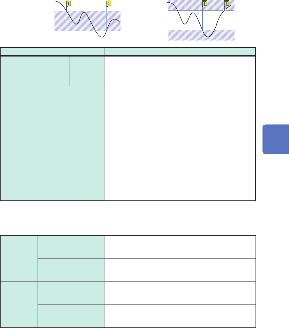
2. [In] trigger, [Out] trigger
When an input signal falls within ([In]) or gets out of a range ([Out]), which is determined by
specifying upper and lower values, an analog trigger is generated.
[In]
Upper limit value
Lower limit value
[Out]
Upper limit value
Lower limit value
Setting Description
Event With OR 1
to 4,000 Allows you to enter the number of events.
The instrument counts the number of times the window-trigger
condition is satised. Only after the count reaches the specied
number of events, an analog trigger is generated.
With AND Not available
Filter Off
,
10 to 10,000
Allows you to enter a lter width in the number of samples.
Only after the window-trigger condition continues to be satised
during the specied period, an analog trigger is generated.
Specifying this option prevents the instrument from being
unintentionally triggered due to noise.
Upper –f.s. to +f.s. Allows you to enter an upper limit value.
Lower –f.s. to +f.s. Allows you to enter a lower limit value.
Auto-
trigger
level*
Off
, On With the [On] setting, the instrument automatically species a
reference level and is triggered when an input signal exceeds
the range between the lower value, the sum of the reference
level and the lower limit value, and the higher value, the sum of
the reference level and the upper limit value. (p. 121)
In [Level of the last time], the reference level used in the
previous measurement appears.
*: Available for the out trigger function only
The operation related to the in and out triggers varies depending on the trigger logical-conditions
(AND and OR).
With OR In The window-trigger condition is satised when an input signal
crosses the upper or lower limit value of the threshold (level)
and thereby falls within the range.
Out The window-trigger condition is satised when an input signal
crosses the upper or lower limit value of the threshold (level)
and thereby gets out of the range.
With AND In The window-trigger condition is satised when an input signal
is inside the range, which is specied by the upper and lower
limit values of the threshold (level).
Out The window-trigger condition is satised when an input signal
is outside the range, which is specied by the upper and lower
limit values of the threshold (level).
5
Conguring the Trigger Settings
110
Triggering the Instrument Using Analog Signals (Analog Trigger)
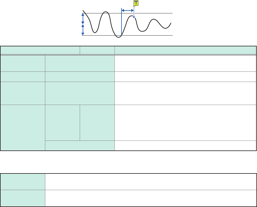
3. [Voltage drop] trigger
When a voltage peak is continuously lower than a specied level for a time of half a period or more,
the voltage-drop-trigger condition is satised. The sampling rate can be set at a gure in the range
of 2 kS/s to 20 MS/s.
These triggers cannot be specied either when Model 8970, Model MR8990, or Model U8991 is
used.
Level
Half the period
Setting Description
Level 0 to +f.s. (100 V
) Allows you to enter a level to be used to check for voltage
drops.
Frequency 50 Hz
, 60 Hz Allows you to specify a power frequency.
RMS (root-
mean-square
value)
Varies in conjunction with
the level settings
Displays a rough indication of the RMS value.
Event With OR 1
to 4,000 Allows you to enter the number of events.
The instrument counts the number of times the voltage-
drop-trigger condition is satised. Only after the count
reaches the specied number of events, an analog trigger
is generated.
With AND Not available
Operations of the voltage drop trigger varies depending on the trigger logical-conditions (AND and OR
operations).
With OR As soon as the instrument determines that a voltage peak is falling below a specied
level for a time of half a period or more, the voltage-drop-trigger condition is satised.
With AND While a voltage peak is lower than a specied level for a time of half a period or longer,
the voltage-drop-trigger condition is continuously satised.