MR8740T_user_manual_eng_20191016H.pdf - 第222页
217 External Sampling (EXT .SMPL) 12.2 External Sampling (EXT .SMPL) Externally inputting the signal can control the sampling rate. How to an input signal 1 Connect each of the EXT .SMPL and GND terminals to an external …
216
External Input and Output
4
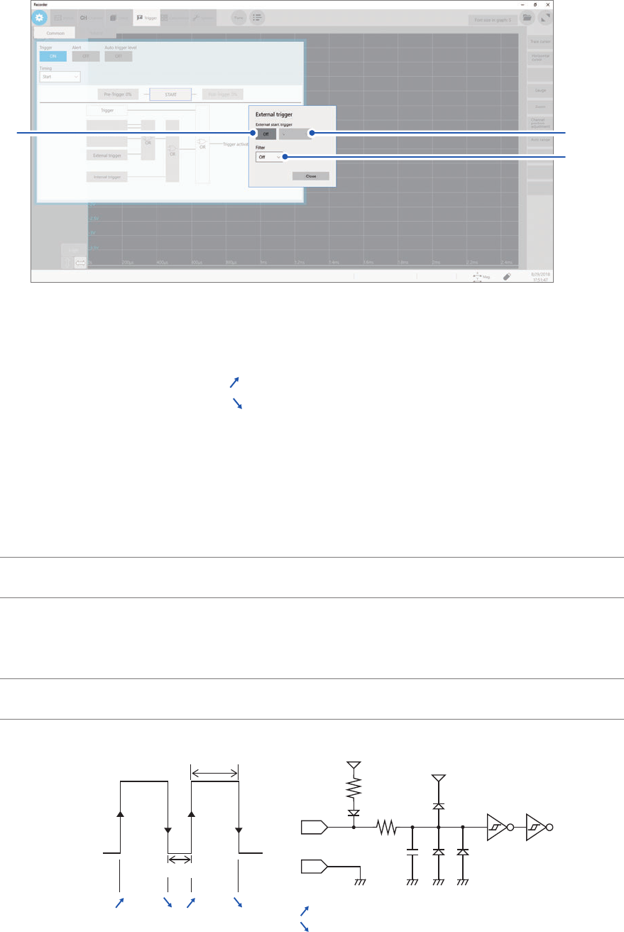
Click [External trigger].
The setting dialog box will appear.
(1)
(2)
(3)
(1) Set [External start trigger] to [On].
(2) Click the box to the right of the [External start trigger] box, and then from the list, choose
which direction to use for reception of the external trigger.
With the rising edge setting: [
]*
With the falling edge setting: [
]*
(3) Click the [Filter] box, and then choose a lter setting from the list.
5
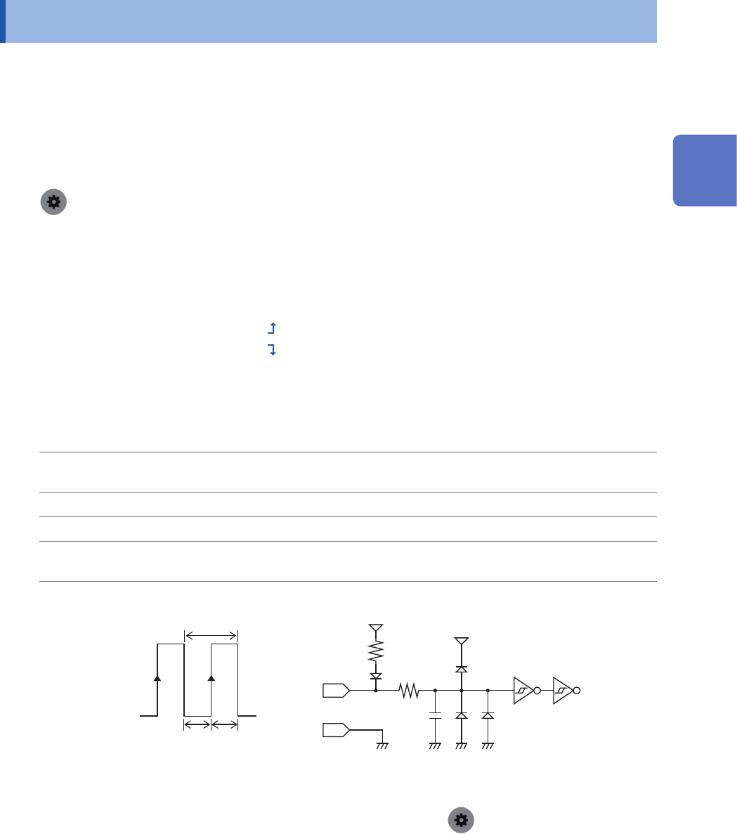
Connect the EXT.TRIG terminal and GND, or input the pulse waves or rectangular waves to
the EXT.TRIG terminal. The signal shall have a high-level voltage of between 2.5 V and 10 V
and a low-level voltage of between 0 V and 0.8 V.
The instrument accepts the external trigger on the rising or falling edge of the input waveform.
Available voltage
range
High level: 2.5 V to 10 V; low level: 0 V to 0.8 V
Pulse width Whit the lter
disabled
High level: 1 ms or more; Low level: 2 μs or more
With the lter
enabled
High and low level: 2.5 ms or more
Maximum input
voltage
10 V DC
[ ]* [ ]*[ ]* [ ]*
[ ]*:
[ ]*:
5 V
EXT. TRIG
5 V
3 kΩ
9 kΩ
22 pF
GND
High
2.5 V to 10 V
Low
0 V to 0.8 V
With the rising edge setting
With the falling edge setting
*: When the trigger logical-condition is set to [AND], [High] or [Low] is displayed.
217
External Sampling (EXT.SMPL)
12.2 External Sampling (EXT.SMPL)
Externally inputting the signal can control the sampling rate.
How to an input signal
1
Connect each of the EXT.SMPL and GND terminals to an external signal-outputting device
with wires.
2
> [Status] > [Condition]
3
Click the [External sampling] button to set it to [On].
4
Click the box to the right of the [External sampling] box, and then from the list, choose
which direction to use for reception of the external sampling signal.
With the rising edge setting: [
]
With the rising edge setting: [
]
5
Input pulse waves or rectangular waves to the EXT.SMPL terminal. The signal shall have a
high-level voltage of between 2.5 V and 10 V and a low-level voltage of between 0 V and 0.8 V.
Available voltage
range
High level: 2.5 V to 10 V; low level: 0 V to 0.8 V
Pulse width High and low level: 50 ns or more
Response frequency 10 MHz or less
Maximum input
voltage
10 V DC
EXT. SMPL 600 Ω
10 pF
5 V
GND
3 kΩ
5 V
t
t
H
t
L
t
H
> 50 ns, t
L
> 50 ns, t > 100 ns
High
2.5 V to 10 V
Low
0 V to 0.8 V
• If a sampling signal with 5 MHz or more is inputted, trigger points are delayed by one sample.
• When Model 8968 High Resolution Unit is used, the anti-aliasing lter (
> [Channel] > [each Unit] >
[A.A.F.]) setting of [On] is invalid.
12
Externally Controlling the Instrument
218
External Sampling (EXT.SMPL)