MR8740T_user_manual_eng_20191016H.pdf - 第67页
62 Conguring Measuring-Module-Specic Settings Congure Model U8979 Charge Unit Settings This setting allows you to choose between voltage measurement and acceleration measurement (charge-output or built-in pre-amplier…
61
Conguring Measuring-Module-Specic Settings
(When you have to choose a current sensor setting) Click the [Mode] box, and then choose
a connected current sensor.
Available measurement ranges, which depend on chosen current sensors, are as follows:
CT7631/CT7731 200 A
CT7636/CT7736 200 A, 400 A, 1 kA
CT7642/CT7742 2 kA, 4 kA
CT7044/CT7045/
CT7046
2 kA, 4 kA, 10 kA
0.1mV/A 2 kA, 4 kA, 10 kA, 20 kA, 40 kA, 100 kA
1mV/A 200 A, 400 A, 1 kA, 2 kA, 4 kA, 10 kA
10mV/A 20 A, 40 A, 100 A, 200 A, 400 A, 1 kA
100mV/A 2 A, 4 A, 10 A, 20 A, 40 A, 100 A
1000mV/A 0.2 A, 0.4 A, 1 A, 2 A, 4 A, 10 A
IMPORTANT
• When Model CT6846 or Model CT6865 connects via Model CT9900 Conversion Cable, the
instrument recognizes the sensor as a 500 A AC/DC sensor. Set the conversion ratio at 2.00 in
the scaling setting.
• When a current sensor included in Model CT6700 series is connected via Model CT9920
Conversion Cable, set a current sensor model name or its output rate.
• Make sure to execute zero-adjustment after you change the setting. Execute zero-adjustment
without any input.
2
(When you have changed the measurement mode) Click [Zero adjust].
The instrument performs zero-adjustment. Execute zero-adjustment without any input.
3
Click the [Range (f.s.)] box, and then choose a measurement range from the list.
The instrument automatically congures the scaling setting for a measurement range according to a
recognized current sensor.
IMPORTANT
The gure of each measurement range name represents the maximum current that Model U8977
can measure using the range. However, the instrument cannot measure currents that exceed the
rated current of a connected current sensor. Check the specications of the current sensor used.
3
Advanced Functions
62
Conguring Measuring-Module-Specic Settings
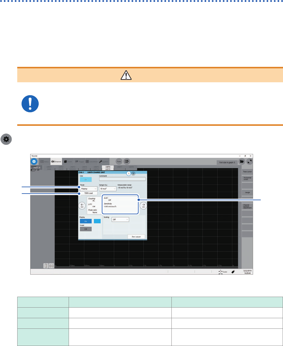
Congure Model U8979 Charge Unit Settings
This setting allows you to choose between voltage measurement and acceleration measurement
(charge-output or built-in pre-amplier) for an input channel.
A channel can measure either one of them.
Voltage mode and Preamp mode use BNC connectors, whereas Charge mode uses miniature
connectors.
Model U8979 can automatically recognize TEDS-compliant* sensors.
*: Transducer electronic data sheet
WARNING
Setting the measurement mode to [Preamp] allows Model U8979 Charge Unit
to constantly provide power (3.5 mA, 22 V) to sensors. Set any measurement
mode other than [Preamp] or tum off the instrument before connecting a sensor
or probe with a BNC terminal to avoid an electric shock or damage to the
measurement target.
> [Channel] > [U8979]
3
1
2
4
5
1
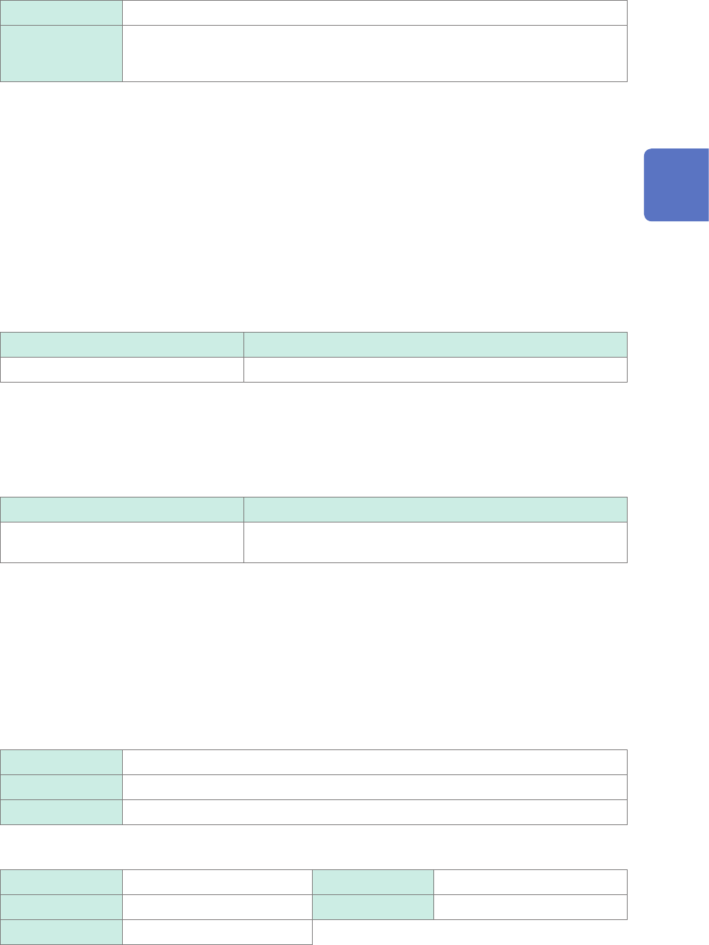
Click the [Mode] box, and then choose a measurement mode from the list.
Mode Measurement target Measurement sensitivity
Voltage Voltage –
Charge
Charge-output acceleration sensor 0.1 pC/(m/s
2
) to 10 pC/(m/s
2
)
Preamp Acceleration sensor with a built-in pre-
amplier
0.1 mV/(m/s
2
) to 10 mV/(m/s
2
)
2
(When setting mode to [Preamp]) Click [TEDS Load].
Acquires sensitivity of a connected sensor. However, the instrument can acquire sensitivity of TEDS-compliant
acceleration sensors with a built-in pre-amplier only.
When sensor sensitivity has been acquired, it is automatically set.
3
Click the area that includes [A.A.F].
The setting dialog box appears.
63
Conguring Measuring-Module-Specic Settings
4
Click the [A.A.F.] box, and then choose a anti-aliasing lter setting from a list.
The anti-aliasing lter can prevent aliasing distortion that may be produced during FFT calculation. The cutoff
frequency automatically changes according to the sampling rates or frequency range (for the FFT function)
settings.
Off
Disables the anti-aliasing lter.
On Enables the anti-aliasing lter.
(Disabled when the external sampling is used, or the sampling rate is set at 100 kS/s
or faster)
5
Click [Sensitivity] box, and then enter sensor sensitivity.
You can enter sensor sensitivity to two decimal places. For a charge-output acceleration sensor or non-TEDS-
compliant sensor, enter its sensitivity marked on the sensor, which represents sensitivity per meter per second
squared.
6
Click [Close].
The setting dialog box closes.
Setting example for sensor sensitivity
Example 1
For a sensor with its sensor sensitivity per meter per second squared marked
Sensor sensitivity Setting value
1.08 pC/(m/s
2
) 1.08
Example 2
For a sensor with its sensor sensitivity per gravity (G) marked.
For a sensor with its sensitivity per gravity (G) marked, enter a quotient of the marked sensitivity
divided by 9.8 m/s
2
.
Sensor sensitivity Setting value
For sensor sensitivity of 64 pC/G
64.0 / 9.8 = 6.53061... pC/(m/s
2
)
6.531 (to two decimal places)
To convert a unit from meter per second squared into gravity (G)
The instrument measures charge quantities per meter per second squared. You can convert such
charge quantities into those per gravity (G) using the scaling function.
Refer to “3.2 Converting Input Values (Scaling Function)” (p. 38).
Congure the scaling setting as follows;
Example 1
Specifying a conversion ratio
Ratio 0.1020E+00 (= 1/9.8)
Offset 0.0000E+00
Units G
Example 2
Specifying two points
Input1 9.8000E+00 Scale1 1.0000E+00
Input2 0.0000E+00 Scale2 0.0000E+00
Units G
3
Advanced Functions