MR8740T_user_manual_eng_20191016H.pdf - 第79页
74 Conguring Generator-Module-Specic Settings Conguring Model U8794 VIR Generator Unit settings Choose [1 1:U8794] . Notch frequency Choose a power frequency according to the power frequency in your region. An incorre…
73
Conguring Generator-Module-Specic Settings
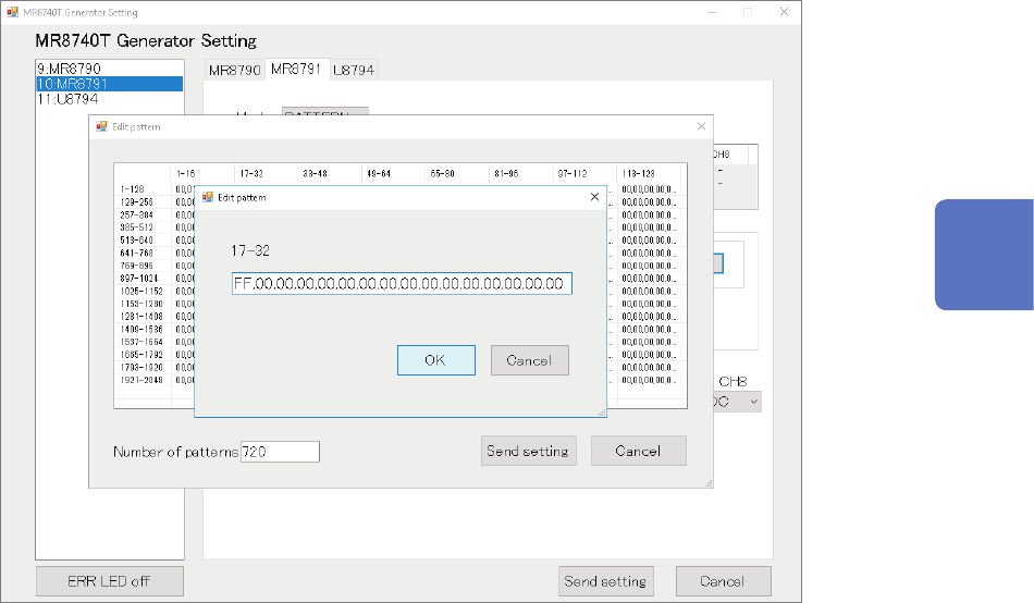
Creating or editing pattern data sets
Clicking a pattern on the screen causes the pattern setting window.
The window allows you to specify the pattern in hexadecimal notation After nishing creating or
editing the pattern, click
[OK]
.
Conrmation of the setting
After nishing the setting, click
[Send setting]
.
The pattern created or edited is stored.
Turning off the instrument clears pattern data sets.
After turning on the instrumen, re-register pattern data.
3
Advanced Functions
74
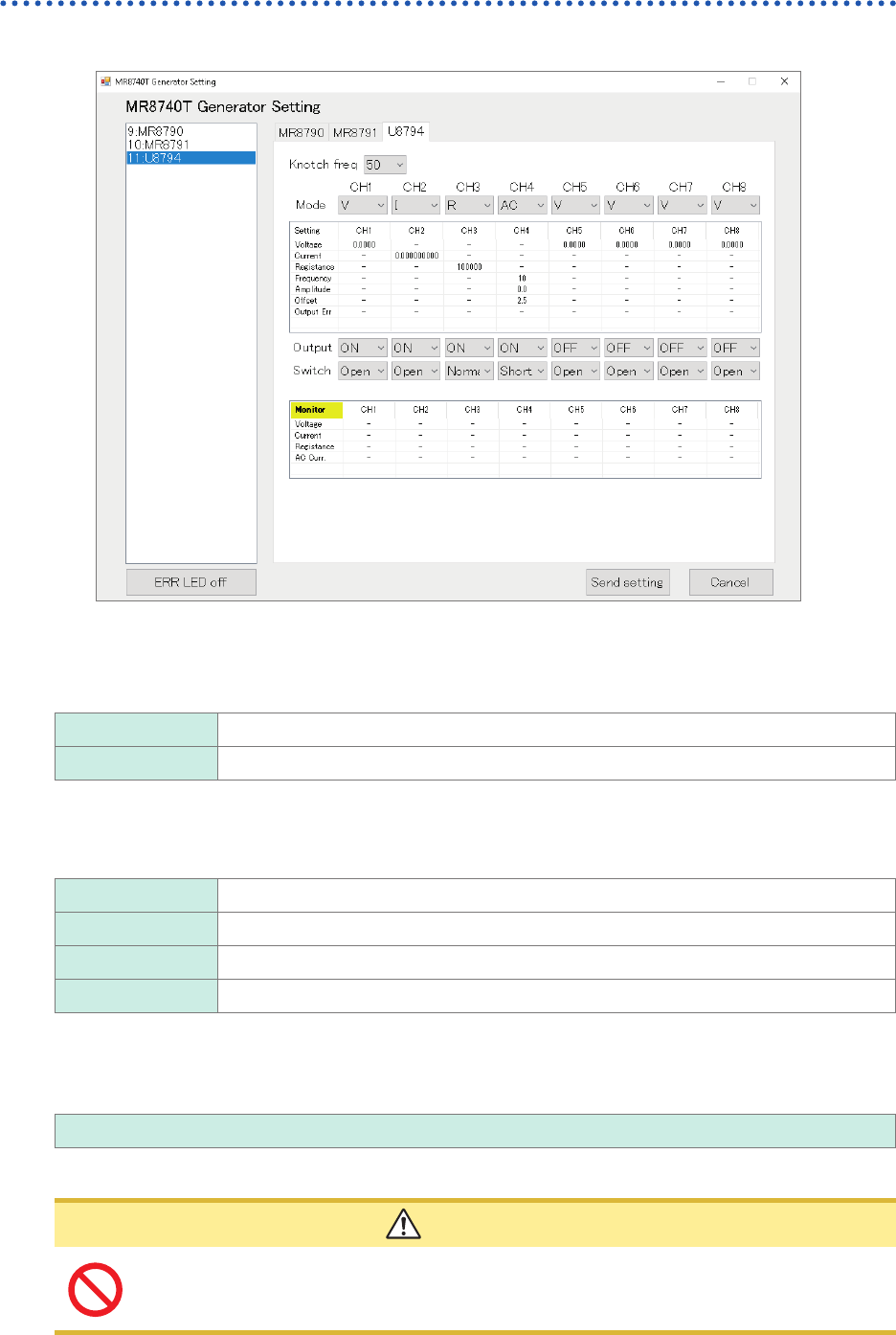
Conguring Generator-Module-Specic Settings
Conguring Model U8794 VIR Generator Unit settings
Choose
[11:U8794]
.
Notch frequency
Choose a power frequency according to the power frequency in your region.
An incorrect power frequency setting causes measured values to be unstable.
50
Allows you to set the notch frequency at 50 Hz.
60 Allows you to set the notch frequency at 60 Hz.
Mode
Allows you to choose an output type.
V
DC voltage
I DC current
R Resistance (simulated)
AC AC voltage
Specifying voltage values
Enter an output DC current value.
−0.1 V to 5.3 V
The output current range of −5 mA to +5 mA.
CAUTION
The instrument accepts a load resistance of 1 k
Ω
or more. Do not connect a load
resistance lower than the permissible value or short-circuit an output terminal. Damage
to the instrument could result.
75
Conguring Generator-Module-Specic Settings
Specifying a voltage value
The instrument outputs a DC current.
−5 mA to +5 mA
The output voltage range is from −0.1 V to +5.3 V.
The instrument switches generation ranges to an appropriate range based on the specied current
value.
−5 mA to −1 mA, 1 mA to 5 mA 5 mA range
−1 mA to −250 µA, 250 µA to 1 mA 1 mA range
−250 µA to −50 µA, 50 µA to 250 mA 250 µA range
−50 µA to 50 µA 50 µA range
Generating resistance
Resistance generation method
The instrument uses an electric circuit to generate resistance on a simulated manner.
The instrument generates a current
I
out
=
V
meas
/ R
set
based on the voltage outputted from the
OUTPUT terminal
V
meas
and a specied resistance value
R
set
.
10
Ω
to 1 M
Ω
IMPORTANT
The instrument cannot generate a set resistance value under any one of the following conditions:
• If the instrument is connected to a measuring instrument that outputs a constant current to
measure the resistance of a measuring object based on the voltage across both ends of the
object
(Example: workbench-type digital multi-meter)
• If the voltage of the OUTPUT terminal exceeds the range of 0 V to 5 V
• If the current outputted from the instrument exceeds the range of −5 mA to 5 mA
Optimizing a resistance generation response
Presuming the characteristic of a measuring object
The resistance generation function of the instrument can presume the characteristic of a measuring
object and optimize a resistance generation response based on the presumed result.
IMPORTANT
• When a connected target has an output resistance of less than 1 k
Ω
, a current that exceeds
the specication will ow, resulting in damage to the instrument and the connected object.
• A time required for presumption varies depending on the characteristic of a connected object. It
must take 1.6 seconds at a maximum.
• When you exchange connected objects, execute presumption of the connected object or
restore the presumption result of the connected object to the default.
Manually optimizing a resistance generation response
You can use the response coefcient command to regulate a response.
Lowering the response coefcient causes a slower response; however, it can prevent oscillations
and overshoots.
IMPORTANT
When you adjust a response coefcient manually, specify an appropriate response coefcient
while observing waveforms with another instrument such as an oscilloscope.
3
Advanced Functions