MR8740T_user_manual_eng_20191016H.pdf - 第18页
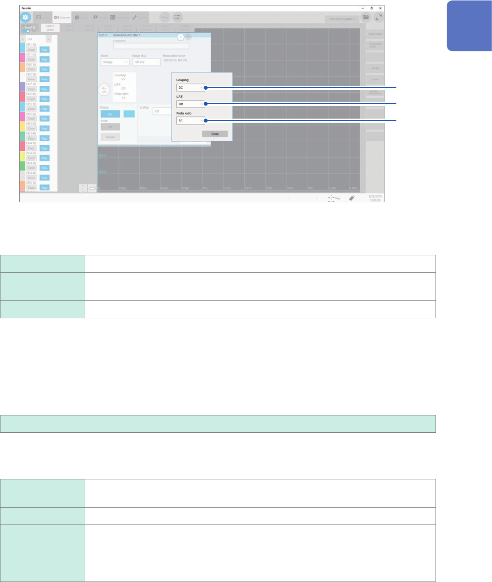
13 Conguring the Input Channel settings 4 Congure the input coupling, low-pass lter , and probe ratio settings. Click the area that includes [Coupling] allows the setting dialog box to appear . (1) (2) (3) (1) Click t…

12
Conguring the Input Channel settings
3
Click the [Range (f.s.)] box, and then choose a measurement range from the list.
Select a measurement range for each channel. The value of the range represents its maximum displayable
value (f.s.).
See the following table for the full-scale resolution of each module.
If the input voltage exceeds the measurable range (overrange occurs), change the measurement range to one
with a lower sensitivity.
For Model MR8990 and Model U8991, starting a measurement using a high-sensitivity range with the input
terminal open causes an input signal to be overrange.
After changing the measurement range, check values of the level, upper limit, lower limit, and other values of
the trigger, search, and numerical calculation functions.
Module Resolution (LSB)
Model 8966 Analog Unit
Model 8971 Current Unit
Model 8972 DC/RMS Unit
2,000
Model 8967 Temp Unit* 20,000
Model 8968 High Resolution Unit
Model U8974 High Voltage Unit
Model U8975 4ch Analog Unit
Model U8977 3CH Current Unit
Model U8978 4CH Analog Unit
32,000
Model U8969 Strain Unit
Model U8979 Charge Unit
25,000
Model 8970 Freq Unit (Power frequency mode) 2,000
Model 8970 Freq Unit (Count mode) 40,000
Model 8970 Freq Unit
(Frequency mode, rotation speed mode, duty ratio mode, pulse width mode)
10,000
Model MR8990 Digital Voltmeter Unit
Model U8991 Digital Voltmeter Unit
1,000,000
*: For the Model 8967 Temp Unit, the valid range varies depending on the thermocouples. For more
information about resolution, refer to “Model 8967 Temp Unit” in “5.2 Specications of the Options” in Quick
Start Manual.
13
Conguring the Input Channel settings
4
Congure the input coupling, low-pass lter, and probe ratio settings.
Click the area that includes [Coupling] allows the setting dialog box to appear.
(1)
(2)
(3)
(1) Click the [Coupling] box, and then choose a coupling method for an input signal from the
list.
Choose a coupling method for an input signal. In general, use the DC coupling.
DC
Measures both DC and AC components of an input signal.
AC Measures an AC component only of an input signal. A DC component can be
eliminated.
GND Connects the input terminal to the ground, which allows you to check the zero position.
(2) (1) Click the [L.P.F] box, and then choose a cutoff frequency of the low-pass lter from the
list.
Enabling the low-pass lter installed in the module can eliminate unwanted high-frequency components.
The lters available vary depending on the module types. Use an adequate lter in accordance with the
characteristics of an input signal.
Example: Model 8966 Analog Unit
OFF
, 5 Hz, 50 Hz, 500 Hz, 5 kHz, 50 kHz, 500 kHz
(3) Click the [Probe ratio] box, and then choose a probe ratio from the list.
Choose any of the ratios when the measurement involves use of a connection cord or probe.
1:1
Choose this ratio when using Model L9197, Model L9198, Model L9790, or Model
L9217 Connection Cord.
1:10 Choose this ratio when using Model 9665 10:1 Probe.
1:100 Choose this ratio when using Model 9666 100:1 Probe, Model P9000-01 Differential
Probe, or Model P9000-02 Differential Probe.
1:1000 Choose this ratio when using Model 9322, Model P9000-01, or Model P9000-02
Differential Probe.
1
Measurement Method

14
Conguring the Input Channel settings
5
Click the [Display] button to set it to [On] or [Off].
On
Displays the waveform on the waveform screen.
Color Allows you to choose a waveform display color. You can also choose the
same color as lines acquired across other channels.
Invert
(Off
, On)
When the signs of displayed waveforms are reversed, the waveforms can be
inverted.
Refer to “3.4 Inverting a Waveform (Invert Function)” (p. 44).
Vernier Allows you to freely ne-adjust the input voltage on the waveform screen
(display adjustment only). When recording physical values such as noise,
temperature, and acceleration with sensors, you can adjust those amplitudes,
facilitating calibration.
Refer to “3.3 Fine-Adjusting Input Values (Vernier Function)” (p. 43).
Off Does not display any waveform.
6
Congure the scaling settings.
Refer to “3.2 Converting Input Values (Scaling Function)” (p. 38).
7
Switch the channels.
Click the corresponding location to switch the channels, and then set the measurement conditions by following
the procedure above.