MR8740T_user_manual_eng_20191016H.pdf - 第82页
77 Conguring Generator-Module-Specic Settings Switching OUTPUT terminals T erminal setting Internal circuit Open Output circuit OUTPUT GND Short Output circuit OUTPUT GND Normal Output circuit OUTPUT GND IMPORT ANT Do …
76
Conguring Generator-Module-Specic Settings
Voltage generation and measurement function
Outputting an AC voltage
The instrument can output a sine wave with a DC voltage superimposed.
DC offset voltage 0.1 V to 2.5 V
Amplitude 0.1 V p-p to 5.0 V p-p
Frequency 10 Hz, 20 Hz, 50 Hz, 100 Hz
CAUTION
The instrument accepts a load resistance of 1 k
Ω
or more. Do not connect a load
resistance lower than the permissible value or short-circuit an output terminal. Damage
to the instrument could result.
IMPORTANT
If you choose a frequency other than the frequencies that can be specied, the instrument sets a
frequency to the one that is the closest.
Output
Switch each output on and off.
OFF
Does not output any waveform.
ON Outputs a waveform.
Switch
You can switch between the short-circuited state and open state for the OUTPUT terminal.
Open Disconnects the OUTPUT terminal from the output circuit and the GND terminal.
Short Connects the OUTPUT terminal with the GND terminal.
Normal Connects the OUTPUT terminal with the internal output circuit.
Conrmation of the setting
After nishing the setting, click
[Apply]
.
The instrument conrms the settings and outputs a waveform.
77
Conguring Generator-Module-Specic Settings
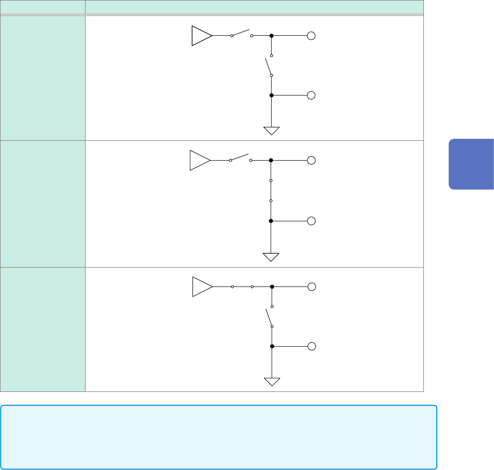
Switching OUTPUT terminals
Terminal setting Internal circuit
Open
Output
circuit
OUTPUT
GND
Short
Output
circuit
OUTPUT
GND
Normal
Output
circuit
OUTPUT
GND
IMPORTANT
Do not set the OUTPUT terminal status to [Short] when a power supply device connects with the
OUTPUT terminal. A short-circuit current will ow, resulting in damage to the instrument or power
supply device.
Self-diagnosis function
Simple test
At the time when you send a query for testing, the instrument measures an output value of the
instrument with the internal measuring circuit and return the specied value and a measured value.
For the voltage output setting, the instrument sends back the specied voltage and a measured
voltage value.
For the current output setting, the instrument sends back the specied current and a measured
current value.
3
Advanced Functions
78
Conguring Generator-Module-Specic Settings
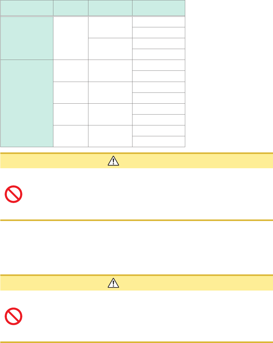
Comprehensive test
The instrument outputs the following voltages and currents of each output function and each
generation range, measuring them with the internal measurement circuit. Then, the instrument
sends back measured values of each output value.
Output item
Generation
range
Measurement
range
Output testing
point
Voltage
5 V 0.5 V 0 V
0.5 V
5 V 0 V
5 V
Current
5 mA 5 mA 5 mA
1.1 mA
1 mA 1 mA 1 mA
275 µA
250 µA 250 µA 250 µA
55 µA
50 µA 50 µA 50 µA
0 µA
CAUTION
Do not connect anything with the OUTPUT terminal during comprehensive tests. The
instrument outputs a zero-volt signal and connects the OUTPUT terminal with the GND
terminal (in the short-circuit state) during comprehensive tests. If a power supply device
connects with the instrument, a short-circuit current will ow, resulting in damage to the
instrument or power supply device. The comprehensive test results may be affected
depending on devices connected.
Offset canceling function
Regulating the zero point of the output circuit
The instrument measures an output circuit offset with the internal measurement circuit and outputs
a value the offset value is subtracted from.
CAUTION
Do not connect anything with the OUTPUT terminal during an offset measurement. The
instrument outputs a zero-volt signal and connects the OUTPUT terminal with the GND
terminal (in the short-circuit state) during the offset measurement. If a power supply
device connects with the instrument, a short-circuit current will ow, resulting in damage
to the instrument or power supply device. The results (zero-point regulation) may be
affected depending on devices connected.