MR8740T_user_manual_eng_20191016H.pdf - 第71页
66 Conguring Generator-Module-Specic Settings 3.7 Conguring Generator-Module-Specic Settings Y ou can congure generator module settings on the dedicated setting screen. Y ou can congure settings of MR8790 Waveform …
65
Conguring Measuring-Module-Specic Settings
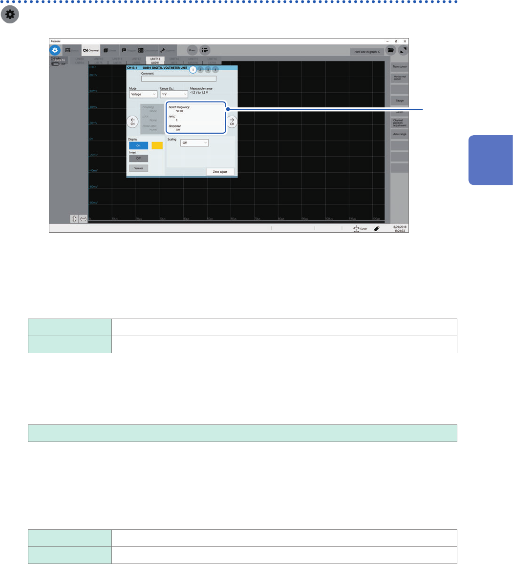
Conguring Model U8991 Digital Voltmeter Unit settings
> [Channel] > [U8991]
to
1
4
1
Click the area that includes [Notch frequency].
The setting dialog box appears.
2
Click the [Notch frequency] box, and then choose a power frequency from the list.
Choose a power frequency of your region.
50 Hz
Sets the period at 20 ms.
60 Hz Sets the period at 16.67 ms.
An incorrect power frequency setting causes measured values to be unstable.
3
Click the [NLPC] box, and then enter an integration time.
Dene an integration time based on the power line cycle (PLC), which is the time equivalent to one period of
the power frequency.
1
, 10, 100
Example: When the power frequency is 50 Hz and NPLC is set at 10, then 20 ms × 10 = 200 ms is obtained.
The instrument updates measured data every 200 ms.
(Increasing NPLC may reduce uctuation in measured values caused due to exogenous noise or an EMC
environment.
4
Click the [Response] box, and then choose a data update interval from the list.
Off
Updates data at intervals the time entered in the [NPLC] box.
On Calculates moving averages every 1 PLC and updates the data.
5
Click [Close].
The setting dialog box closes.
3
Advanced Functions
66
Conguring Generator-Module-Specic Settings
3.7 Conguring Generator-Module-Specic Settings
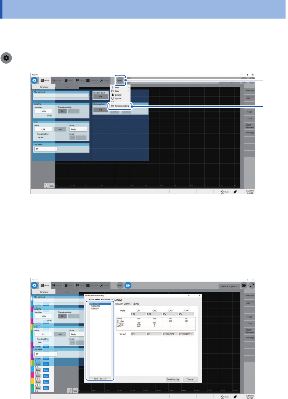
You can congure generator module settings on the dedicated setting screen.
You can congure settings of MR8790 Waveform Generator Unit, MR8791 Pulse Generator Unit,
and U8794 VIR Generator Unit using the instrument.
>[Func]> [Generator Setting].
2
1
1
Click [Func].
2
Click [Generator Setting].
The setting screen dedicated for the generator modules.
The slots generator modules are installed in and model names are displayed in the left-hand side of
the setting screen
Slots in which generator modules are installed cannot be used for measurement.
67
Conguring Generator-Module-Specic Settings
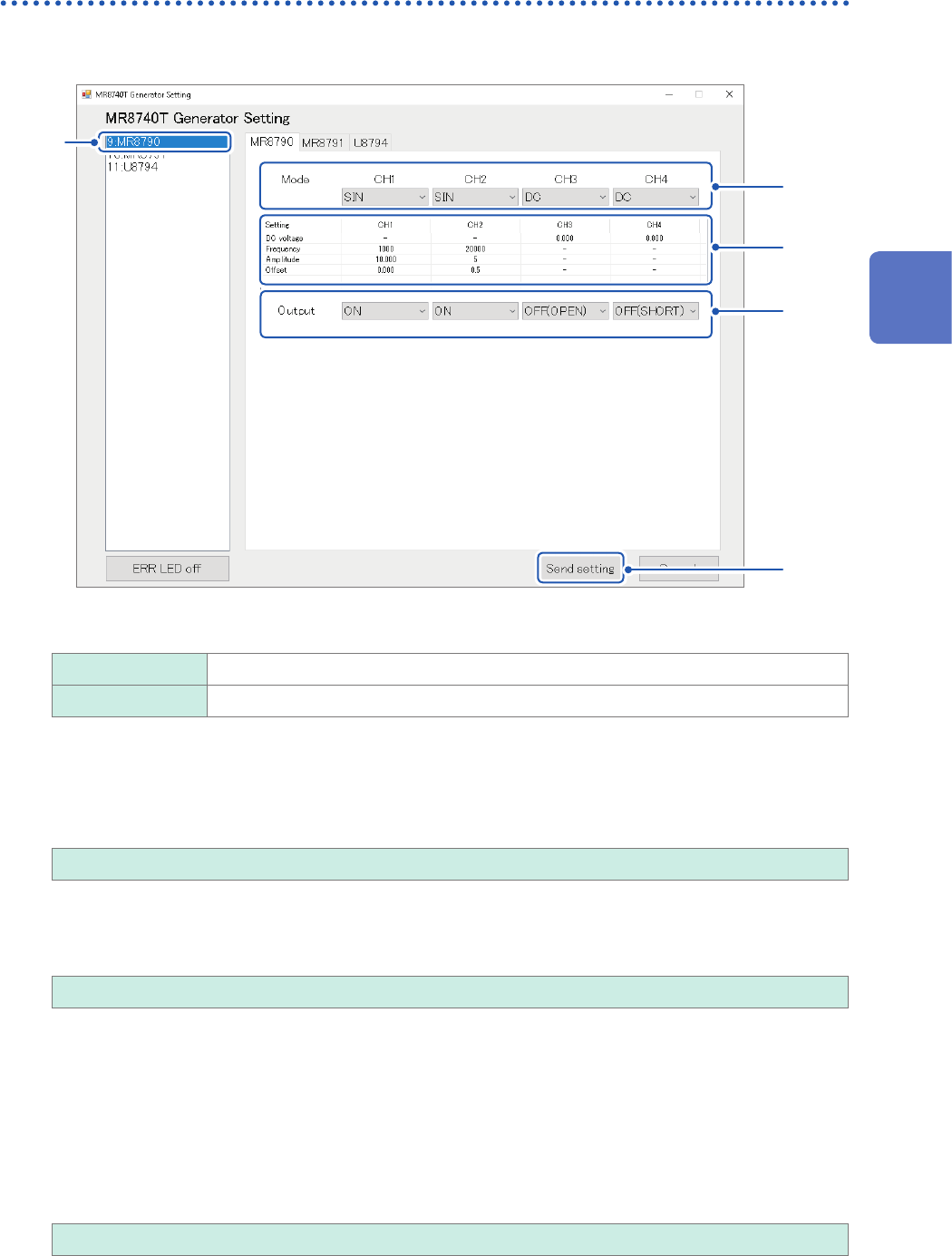
Conguring Model MR8790 Waveform Generator Unit setting
1
Click [MR8790].
5
1
3
2
4
2
Allows you to choose a waveform type
DC
Outputs a DC signal.
SIN Outputs a sine wave signal.
3
Congure the advanced output settings.
DC voltage
Allows you to enter a DC voltage.
−10.000 V to +10.000 V
Frequency
Allows you to enter a frequency of the output sine wave.
0 Hz to 20000 Hz
Amplitude
Allows you to enter an amplitude of the output sine wave.
Accuracy of the output voltage, which consists of amplitude and an offset value, is guaranteed in the
range of −10 V to +10 V.
An output waveform will appear with its upper parts limited to about +14 V and lower about
−14 V when the sum of the amplitude and offset value is set to out of the accuracy-guaranteed
range.
0.000 V p-p to 20.000 V p-p
3
Advanced Functions