MR8740T_user_manual_eng_20191016H.pdf - 第5页
Contents iv

Contents
iii
12 Externally Controlling
the Instrument
209
12.1 External Input and Output
.................210
External input (IN1), (IN2)
.......................210
External output (OUT1), (OUT2)
..............211
Trigger output (TRIG.OUT)
......................213
External trigger terminal (EXT.TRIG)
.......215
12.2 External Sampling (EXT.SMPL)
.......217
13 Appendix 219
13.1 Information for Reference
Purposes
..............................................219
Waveform le size
(values for reference purposes)
...............219
Maximum recordable time when the
real-time save is enabled
(values for reference purposes)
...............221
Scaling method for strain gauges
............223
Example of a waveform text le
...............225
Index 227
9
8
7
6
5
Index
13
12
11
10
Contents
iv
1
Introduction
Thank you for choosing the Hioki MR8740T Memory HiCorder (Model MR8740-50). Preserve this
manual carefully and keep it handy to make full use of this instrument for a long time.
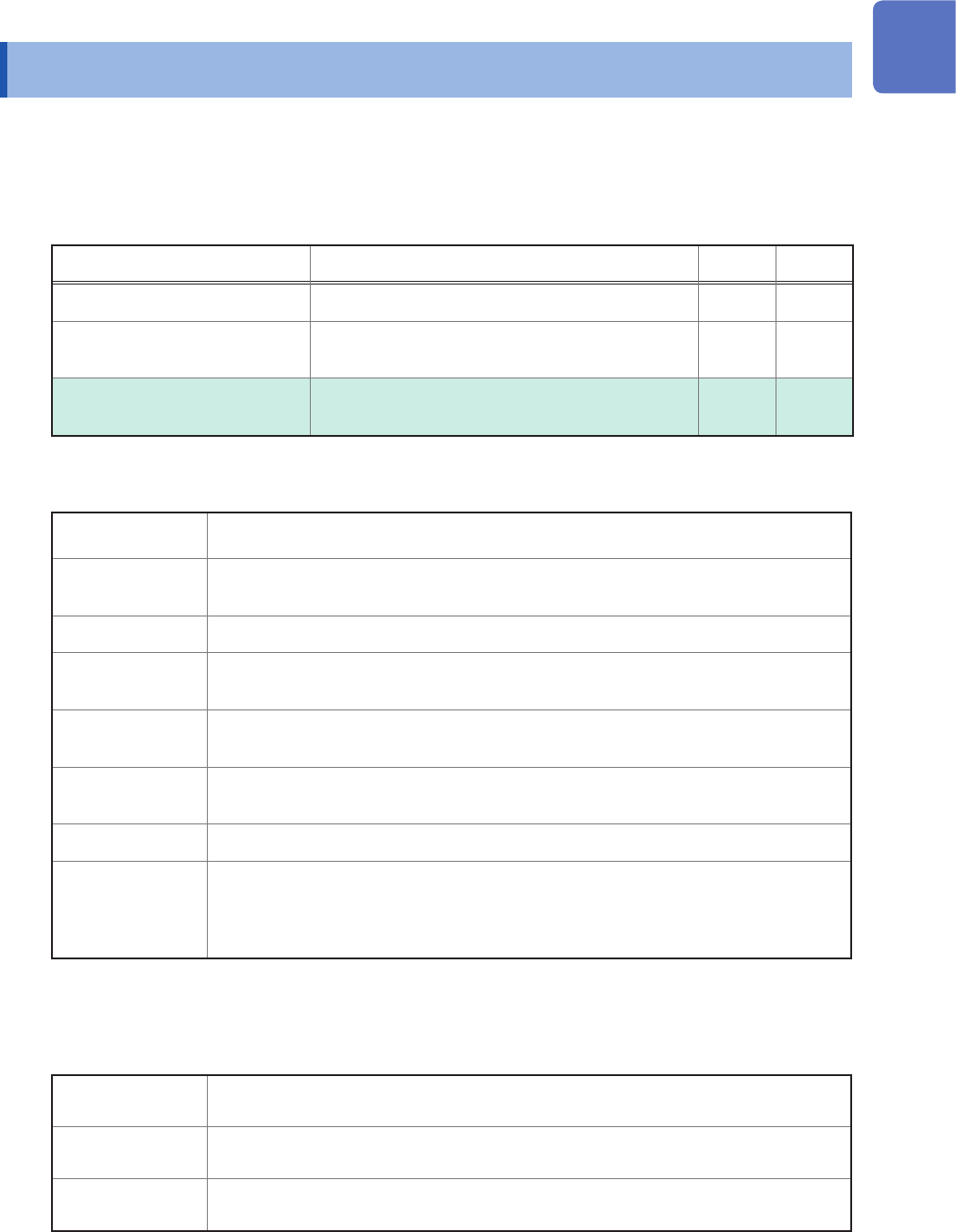
Following manuals are provided along with these models. Refer to manuals relevant to your
purpose.
Type Contents Printed PDF
Operating Precautions Information on the instrument for safe operation
–
Quick Start Manual
Basic instructions and specications of the
instrument
–
Instruction Manual (this
document)
Functions and instructions for the instrument –
Notations
*
Additional information is presented below.
Indicates the initial setting values of the items. Initializing the instrument restores
settings to each of these values.
(p. ) Indicates the location of reference information.
START
(Bold-faced)
Names and keys on the screen are shown in boldface.
[ ]
Menus, dialog boxes, buttons in a dialog box, and other names on the screen are
indicated in brackets ([ ]).
Windows
Unless otherwise specied, “Windows” represents Windows 7, Windows 8, and
Windows 10.
Current sensor Sensors measuring current are referred to as “current sensor.”
S/s
The number of times per second the analog input signals are digitized by the
instrument is represented in “samples per second (S/s).”
Example: “20 MS/s” (20 megasamples per second) indicates that the signal is digitized
20 × 10
6
times per second.
Accuracy
We dene measurement tolerances in terms of f.s. (full scale) and rdg. (reading) values, with the
following meanings:
f.s.
(maximum display value or scale length)
The maximum displayable value or scale length.
rdg.
(displayed value)
The value currently being measured and displayed on the measuring instrument.
setting
(setting value)
Indicates the value set as the output voltage, current, or other quantity.
Introduction