MR8740T_user_manual_eng_20191016H.pdf - 第76页
71 Conguring Generator-Module-Specic Settings Pattern reproducing frequency Enter a clock frequency of pulse pattern. (In 10 Hz increments) • Settable clock period range: 0 to 0.1 seconds • Y ou can freely specify the …
70
Conguring Generator-Module-Specic Settings
4
Output conguration (Method)
You can congure the output settings.
The ground potential is cross-channel and not insulated.
With the open-collector output setting
• Limit the collector-emitter voltage to 50 V.
• Output signals require a response time of about 5 µs or less to rise from 10% to 90%. (With a load capacity
of 1000 pF and a pull-up resistamce of 1 k
Ω
, values for reference purposes)
TTL
TTL-level output (amplitude: 0-5 V)
OC Open-collector output
5
Output
Allows you to switch waveform output settings.
The instrument may momentary output a high-level signal at the times of power-on and power-off.
OFF
Does not output any waveform
ON Outputs a waveform
6
Conrmation of the setting
After nishing the setting, click
[Send setting]
.
The instrument conrms the settings and outputs a waveform.
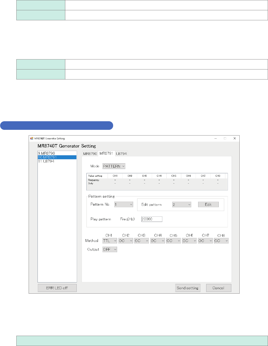
Conguring the pattern output settings
Pattern number
Enter an pattern number.
• When no output is enabled, the instrument outputs the pattern signal registered rst.
• Turning off the instrument clears pattern data sets. After turning on the instrument, re-register pattern data
set.
1 to 16

71
Conguring Generator-Module-Specic Settings
Pattern reproducing frequency
Enter a clock frequency of pulse pattern. (In 10 Hz increments)
• Settable clock period range: 0 to 0.1 seconds
• You can freely specify the clock cycle as long as it falls into the above-mentioned range. The cycle of the
actually outputted waveform becomes the nearest value among the reciprocals of settable frequencies.
0 Hz to 120000 Hz
Output conguration
Choose an output status.
• The ground potential is cross-channel and not insulated.
TTL
TTL-level output (amplitude: 0-5 V)
OC Open-collector output
With the open-collector output setting
• Limit the collector-emitter voltage to 50 V.
• Output signals require a response time of about 5 µs or less to rise from 10% to 90%. (With a load capacity
of 1000 pF and a pull-up resistance of 1 k
Ω
, values for reference purposes)
Output
Switch waveform output settings.
The instrument may momentary output a high-level signal at the times of power-on and power-off.
OFF
Does not output a waveform
ON Outputs a waveform
Conrmation of the setting
After nishing the setting, click
[Send setting]
.
The instrument conrms the settings and outputs a waveform.
3
Advanced Functions
72
Conguring Generator-Module-Specic Settings
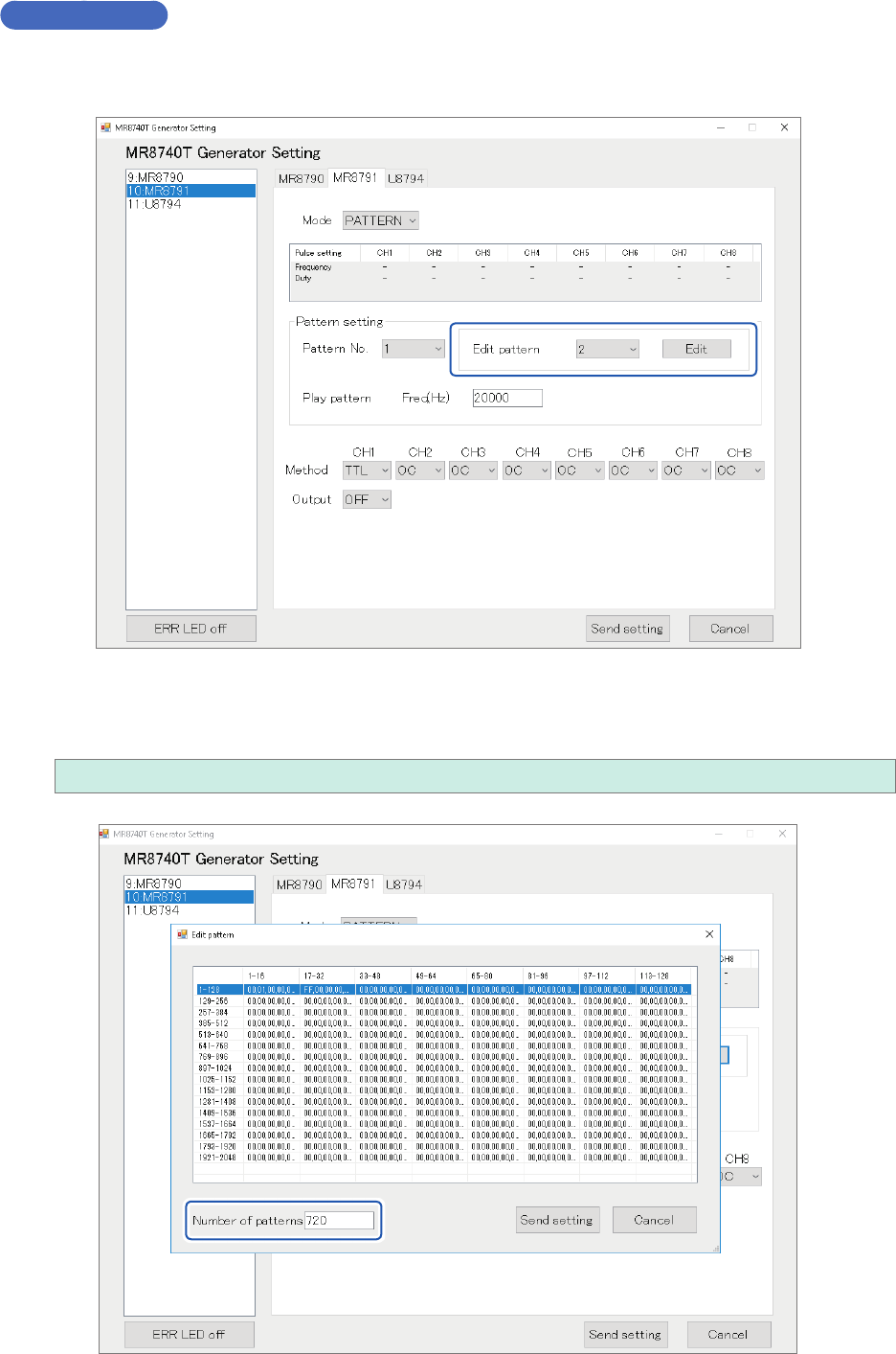
Editing patterns
Editing patterns
Choose a pattern number you want to create or edit, and then click [Edit].
Number of pattern data sets
Enter the number of pattern data sets you want to create or edit.
1 to 2048