MR8740T_user_manual_eng_20191016H.pdf - 第68页
63 Conguring Measuring-Module-Specic Settings 4 Click the [A.A.F .] box, and then choose a anti-aliasing lter setting from a list. The anti-aliasing lter can prevent aliasing distortion that may be produced during FF…
62
Conguring Measuring-Module-Specic Settings
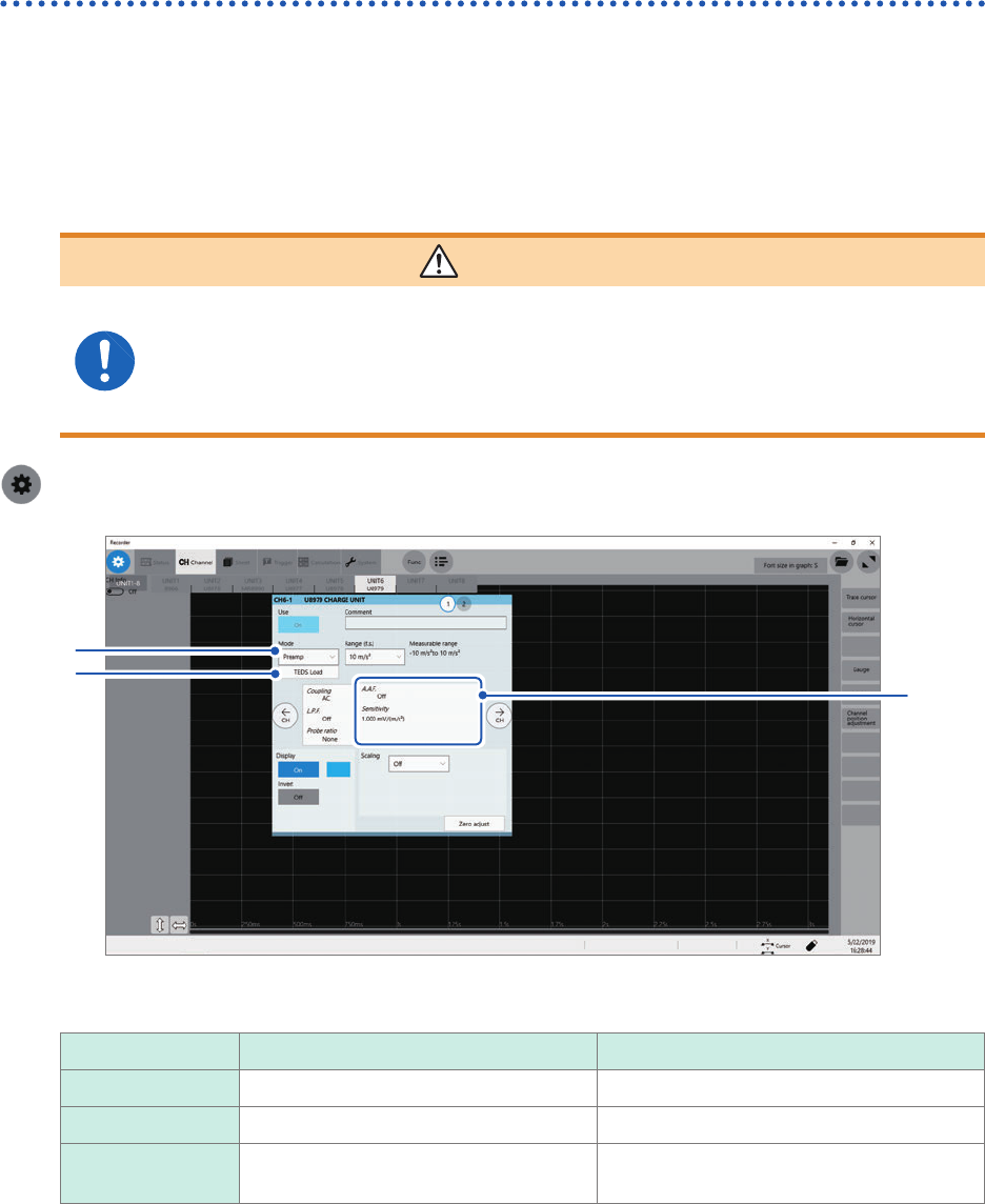
Congure Model U8979 Charge Unit Settings
This setting allows you to choose between voltage measurement and acceleration measurement
(charge-output or built-in pre-amplier) for an input channel.
A channel can measure either one of them.
Voltage mode and Preamp mode use BNC connectors, whereas Charge mode uses miniature
connectors.
Model U8979 can automatically recognize TEDS-compliant* sensors.
*: Transducer electronic data sheet
WARNING
Setting the measurement mode to [Preamp] allows Model U8979 Charge Unit
to constantly provide power (3.5 mA, 22 V) to sensors. Set any measurement
mode other than [Preamp] or tum off the instrument before connecting a sensor
or probe with a BNC terminal to avoid an electric shock or damage to the
measurement target.
> [Channel] > [U8979]
3
1
2
4
5
1
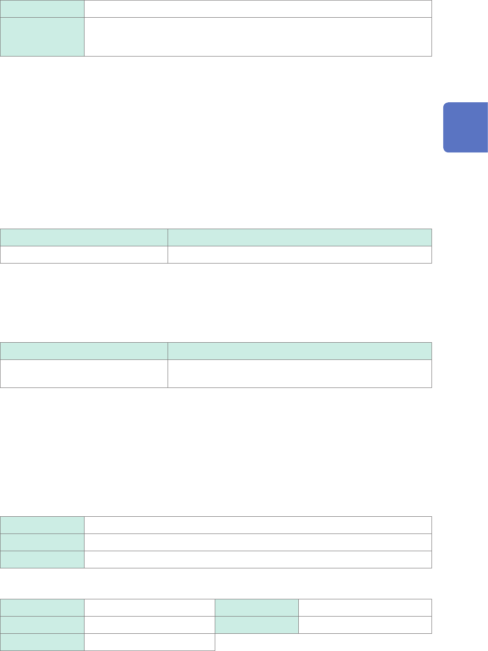
Click the [Mode] box, and then choose a measurement mode from the list.
Mode Measurement target Measurement sensitivity
Voltage Voltage –
Charge
Charge-output acceleration sensor 0.1 pC/(m/s
2
) to 10 pC/(m/s
2
)
Preamp Acceleration sensor with a built-in pre-
amplier
0.1 mV/(m/s
2
) to 10 mV/(m/s
2
)
2
(When setting mode to [Preamp]) Click [TEDS Load].
Acquires sensitivity of a connected sensor. However, the instrument can acquire sensitivity of TEDS-compliant
acceleration sensors with a built-in pre-amplier only.
When sensor sensitivity has been acquired, it is automatically set.
3
Click the area that includes [A.A.F].
The setting dialog box appears.
63
Conguring Measuring-Module-Specic Settings
4
Click the [A.A.F.] box, and then choose a anti-aliasing lter setting from a list.
The anti-aliasing lter can prevent aliasing distortion that may be produced during FFT calculation. The cutoff
frequency automatically changes according to the sampling rates or frequency range (for the FFT function)
settings.
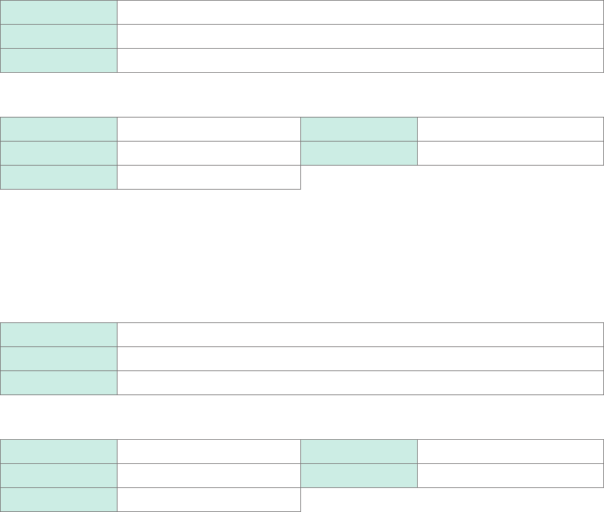
Off
Disables the anti-aliasing lter.
On Enables the anti-aliasing lter.
(Disabled when the external sampling is used, or the sampling rate is set at 100 kS/s
or faster)
5
Click [Sensitivity] box, and then enter sensor sensitivity.
You can enter sensor sensitivity to two decimal places. For a charge-output acceleration sensor or non-TEDS-
compliant sensor, enter its sensitivity marked on the sensor, which represents sensitivity per meter per second
squared.
6
Click [Close].
The setting dialog box closes.
Setting example for sensor sensitivity
Example 1
For a sensor with its sensor sensitivity per meter per second squared marked
Sensor sensitivity Setting value
1.08 pC/(m/s
2
) 1.08
Example 2
For a sensor with its sensor sensitivity per gravity (G) marked.
For a sensor with its sensitivity per gravity (G) marked, enter a quotient of the marked sensitivity
divided by 9.8 m/s
2
.
Sensor sensitivity Setting value
For sensor sensitivity of 64 pC/G
64.0 / 9.8 = 6.53061... pC/(m/s
2
)
6.531 (to two decimal places)
To convert a unit from meter per second squared into gravity (G)
The instrument measures charge quantities per meter per second squared. You can convert such
charge quantities into those per gravity (G) using the scaling function.
Refer to “3.2 Converting Input Values (Scaling Function)” (p. 38).
Congure the scaling setting as follows;
Example 1
Specifying a conversion ratio
Ratio 0.1020E+00 (= 1/9.8)
Offset 0.0000E+00
Units G
Example 2
Specifying two points
Input1 9.8000E+00 Scale1 1.0000E+00
Input2 0.0000E+00 Scale2 0.0000E+00
Units G
3
Advanced Functions
64
Conguring Measuring-Module-Specic Settings
When using an out-of-setting-range current sensor
You can use an out-of-setting-range current sensor using the scaling function.
Refer to “Automatically saving waveform data” (p. 84).
1
Click the area that includes [Sensitivity].
The setting dialog box appears.
2
Click [Sensitivity] box, and then enter sensor sensitivity.
Multiply the sensor sensitivity of a sensor to be used by a certain value to allow a product to fall within the
setting range (0.1 to 10), and enter the product.
3
Click [Close].
The setting dialog box closes.
4
Click the [Scaling] box, and then congure the scaling setting.
Congure the scaling setting so that a scaling ratio is the same value as the number you multiplied the sensor
sensitivity by.
Example 1
For sensor sensitivity of 23.4 pC/(m/s
2
)
Specify 10 pC/(m/s
2
), which results from multiplying the sensor sensitivity by 1/2.34, as the sensor sensitivity.
To display measured values after multiplying them by 1/2.34, congure the scaling setting as follows:
To congure the scaling setting using the conversion ratio method
Ratio 0.4274E+00 (= 10/23.4)
Offset 0.0000E+00
Units m/s
2
To congure the scaling setting using the 2-point method
Input1 2.3400E+00 Scale1 1.0000E+00
Input2 0.0000E+00 Scale2 0.0000E+00
Units m/s
2
Example 2
For sensor sensitivity of 0.05 pC/(m/s
2
)
Specify 0.1 pC/(m/s
2
), which results from multiplying the sensor sensitivity by two, as the sensor sensitivity.
To display measured values after multiplying them by two, congure the scaling setting as follows:
To congure the scaling setting using the conversion ratio method
Ratio 2.0000E+00 (= 0.1/0.05)
Offset 0.0000E+00
Units m/s
2
To congure the scaling setting using the 2-point method
Input1 0.0500E+00 Scale1 1.0000E+00
Input2 0.0000E+00 Scale2 0.0000E+00
Units m/s
2