MR8740T_user_manual_eng_20191016H.pdf - 第117页
11 2 T riggering the Instrument Using Analog Signals (Analog T rigger) Setting of the period range The period range settings of the period trigger vary depending on the sampling periods (sampling rates). (The setting val…
111
Triggering the Instrument Using Analog Signals (Analog Trigger)
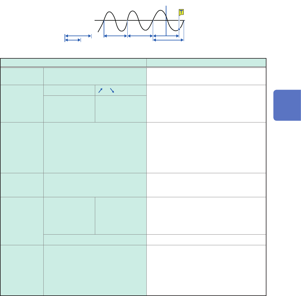
4. [Period-in] trigger and [Period-out] trigger
The instrument measures periods of an input waveform, which are time lags between consecutive
two points at which an input voltage crosses the specied level in the positive or negative direction.
The period-trigger condition is satised when a period is inside the specied range (In) or outside
the specied range (Out).
An trigger point lags behind the actual trigger point by one sample.
These triggers cannot be specied either when Model 8970, Model MR8990, or Model U8991 is
used.
Refer to “Setting of the period range” (p. 112) and “[Period-out] trigger” (p. 112).
Level
Period upper limit
Period lower limit
Upper limit value
Out of the range
Within the period range
Setting Description
Level –f.s. to +f.s.
Default: 0
Allows you to enter a level for detecting the
rising or falling slopes of a signal.
Slope With OR
, Allows you to choose which of the following
points to use to calculate periods: two
consecutive points at which a signal crosses
the specied level in the positive direction; or
those in the negative direction.
With AND HIGH
, LOW
Period lower
limit*
Zero or 5 times the sampling period
or longer
The lower limit of periods cannot be set to a
value higher than that in the [Period upper
limit] box. When the lower limit of periods is
set at [0], the instrument ignores the value in
the [Period lower limit] box, and the period-
trigger condition is satised using the value in
the [Period upper limit] box only.
Period upper
limit*
20,000 times or less of the sampling
period
The higher limit of periods cannot be set to
a value lower than that in the [Period lower
limit] box.
Event With OR 1
to 4,000 Allows you to enter the number of events.
The instrument counts the number of times
the period-trigger condition is satised. Only
after the count reaches the specied number of
events, an analog trigger is generated.
With AND Not available
Filter Off
, 10 to 10,000 Allows you to enter a lter width in the number
of samples. Only after the period-trigger
condition is continuously satised during the
specied period, an analog trigger is generated.
Specifying this option prevents the instrument
from being unintentionally triggered due to
noise.
*: Ranges of values that can be set in the period lower limit and period upper limit boxes varies in conjunction
with the sampling rates (periods).
5
Conguring the Trigger Settings
112
Triggering the Instrument Using Analog Signals (Analog Trigger)
Setting of the period range
The period range settings of the period trigger vary depending on the sampling periods (sampling
rates).
(The setting value of the period range also changes in conjunction with the sampling period [sampling
rate] setting.)
Select [Status] > [Condition] > [Sampling] and check the sampling rate setting.
To set the period-trigger condition such that it is satised when an input frequency exceeds
the upper limit value (when the period becomes shorter)
Set [Type] to [Period-in] and set [Period lower limit] at [0]. The instrument ignores a value in
the [Period lower limit] box, and the period-trigger condition is satised when an input frequency
exceeds a value in the [Period upper limit] box.
To set the period-trigger condition such that only when an input frequency falls below the
upper limit value (when the period becomes longer):
Set [Type] to [Period-out] and set [Period lower limit] at [0]. The instrument ignores a value in
the [Period lower limit] box, and the period-trigger condition is satised when an input frequency
falls below a value in the [Period upper limit] box.
[Period-out] trigger
The instrument calculates periods by monitoring times when an input signal crosses the specied
level in the positive or negative direction, and the period-trigger condition is satised when a period
gets out of the specied period range.
Points at which the period-trigger condition is satised varies depending on the specied period
range and the period of a measuring object.
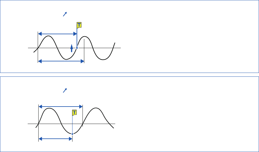
When an input signal period is shorter than the specied lower limit of periods (with the
slope set to positive [ ]).
Level at
time
Period of the input signal
Period lower limit
The period-trigger condition is satised when a rising
slope of an input signal crosses the specied level
before the lower limit of periods elapses.
When an input signal period is longer than the specied upper limit of periods (with the
slope set to positive [ ])
Period of the input signal
Period upper limit
Level
The period-trigger condition is satised when the upper
limit of periods elapses before a rising slope of an input
signal crosses the reference voltage level.
Thus, points at which the period-out-trigger condition is
satised varies depending on the upper limit of a period
range.
113
Triggering the Instrument Using Analog Signals (Analog Trigger)
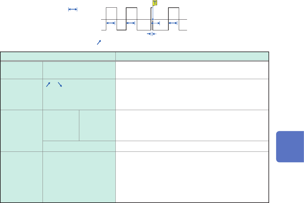
5. [Glitch] trigger
The glitch-trigger condition is satised when a pulse width of an input signal that has crossed the
specied level is shorter than the specied duration.
These triggers cannot be set either when Model MR8990 or Model U8991 is used.
Width
Level
Input waveform
Slope: [
]
Setting Description
Level –f.s. to +f.s.
Default: 0
Allows you to specify the level for detecting glitches.
Slope
, Allows you to choose which of the following points to use
to detect glitches: two consecutive points at which a signal
crosses the specied level in the positive direction; or those
in the negative direction.
Event With OR 1
to 4,000 Allows you to enter the number of events.
The instrument counts the number of times the glitch-trigger
condition is satised. An analog trigger is generated only
after the count reaches the specied number of events.
With AND Not available
Width 2 times to 4000 times of
the sampling period
Allows you to enter a pulse width (time), which is used to
determine a glitch.
The glitch-trigger condition is satised when a pulse width is
shorter than the specied width. (The available setting range
varies depending on the sampling periods. Lower limit: 2
times sampling period or longer; Upper limit: 4000 times
sampling period or shorter)
5
Conguring the Trigger Settings