MR8740T_user_manual_eng_20191016H.pdf - 第61页
56 Conguring Measuring-Module-Specic Settings Conguring Model 8972 DC/RMS Unit settings > [Channel] > [8972] 3 1 2 1 In the [Mode] area, click the [DC] or [RMS] to choose a measurement mode. DC For voltage mea…

55
Conguring Measuring-Module-Specic Settings
4
Click the [Range (f.s.)] box, and then choose a measurement range from the list.
IMPORTANT
The gure of each measurement range name represents the maximum current Model 8971 can
measure using the range. However, the instrument cannot measure currents that exceed the rated
current of a connected current sensor. Check the specications of the current sensor used.
3
Advanced Functions
56
Conguring Measuring-Module-Specic Settings
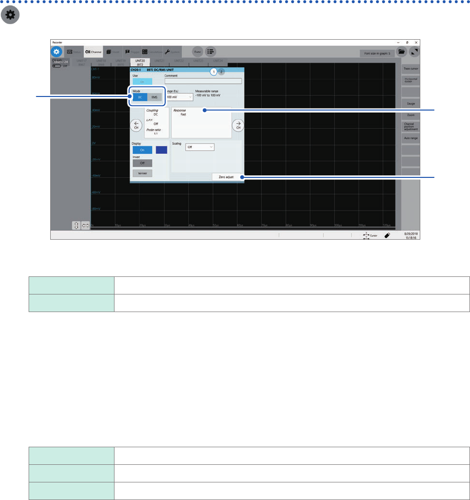
Conguring Model 8972 DC/RMS Unit settings
> [Channel] > [8972]
3
1
2
1
In the [Mode] area, click the [DC] or [RMS] to choose a measurement mode.
DC
For voltage measurement
RMS For RMS measurement
2
(When you have changed the measurement mode) Click [Zero adjust].
The instrument performs zero-adjustment. Execute zero-adjustment without any input.
3
Click the area that includes [Response].
The setting dialog box appears.
4
Click the [Response] box, and then from the list, choose a response time for RMS
measurement.
Fast
Sets the response time to about 100 ms.
Normal Sets the response time to about 800 ms.
Slow Sets the response time to about 5 seconds.
Usually, use [Fast]. Setting the response time to [Normal] or [Slow] can stabilize the measured values if the
frequency is relatively low or the voltage uctuates severely.
5
Click [Close].
The setting dialog box closes.
57
Conguring Measuring-Module-Specic Settings
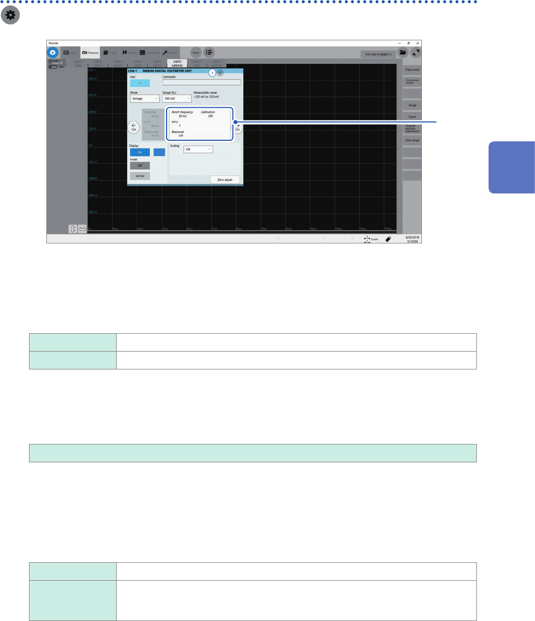
Conguring Model MR8990 Digital Voltmeter Unit settings
> [Channel] > [MR8990]
to
1
5
1
Click the area that includes [Notch frequency].
The setting dialog box appears.
2
Click the [Notch frequency] box, and then choose a power frequency from the list.
Choose a power frequency of your region.
50 Hz
Sets the period at 20 ms.
60 Hz Sets the period at 16.67 ms.
An incorrect power frequency setting causes measured values to be unstable.
3
Click the [NLPC] box, and then enter an integration time.
Dene an integration time based on the power line cycle (PLC), which is the time equivalent to one period of
the power frequency.
0.1 to 0.9, 1
to 10, 20, 30, 40, 50, 60, 70, 80, 90, 100
Example: When the power frequency is 50 Hz and NPLC is set at 10, then 20 ms × 10 = 200 ms is obtained.
The instrument updates measured data every 200 ms.
(Increasing NPLC may reduce uctuation in measured values caused due to exogenous noise or an EMC
environment.)
4
Click the [Response] box, and then choose a data update interval from the list.
Data can be updated at high speed.
Off
Updates data at intervals or input the integration time entered in the [NPLC] box.
On Updates the data at high speed by calculating moving averages.
• Updates data at intervals of 0.1 PLC when NPLC is set at 9 or less.
• Updates data at intervals of 1 PLC when NPLC is set at 10 or more.
3
Advanced Functions