MR8740T_user_manual_eng_20191016H.pdf - 第19页
14 Conguring the Input Channel settings 5 Click the [Display] button to set it to [On] or [Off] . On Displays the waveform on the waveform screen. Color Allows you to choose a waveform display color . Y ou can also ch…
13
Conguring the Input Channel settings
4
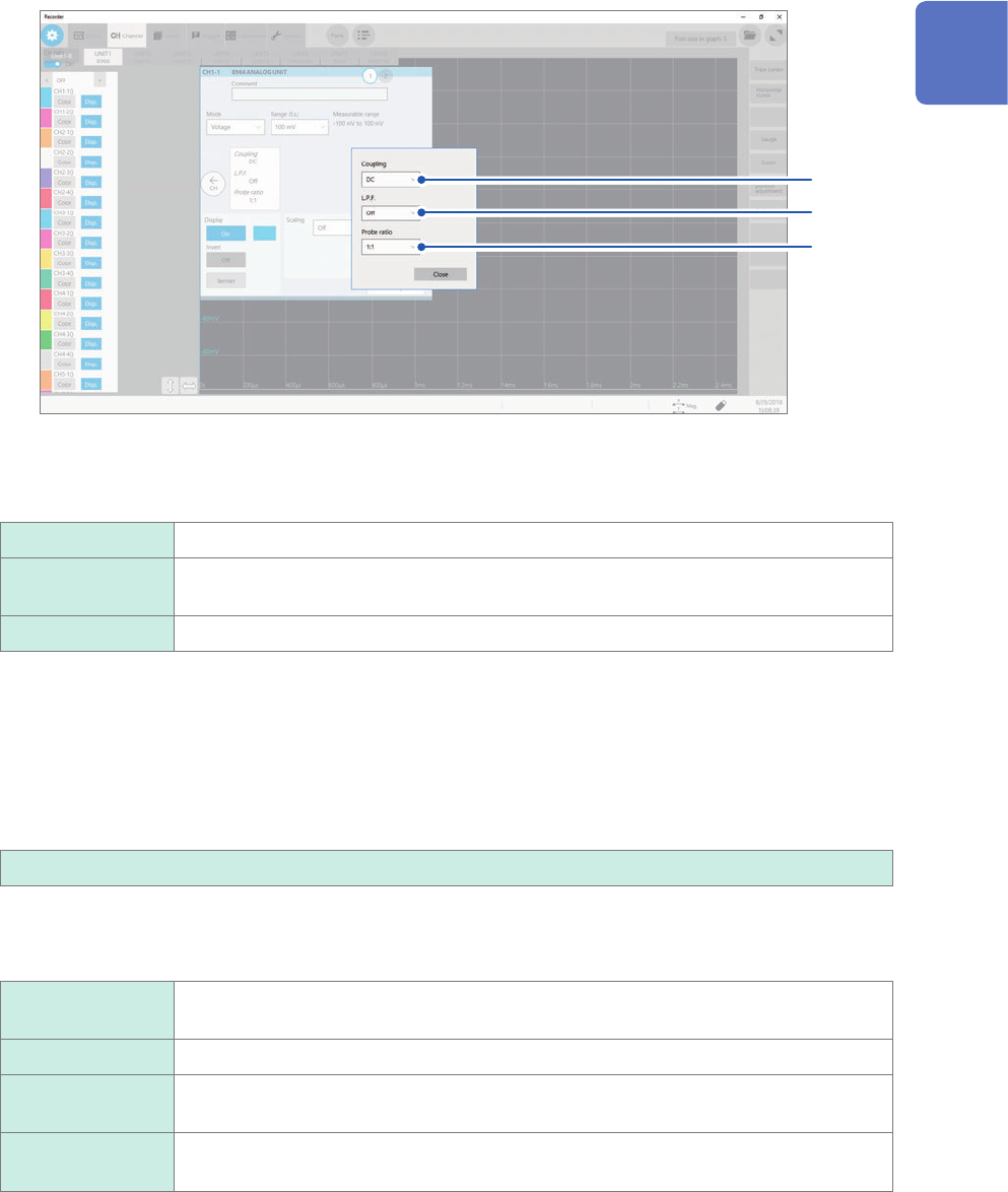
Congure the input coupling, low-pass lter, and probe ratio settings.
Click the area that includes [Coupling] allows the setting dialog box to appear.
(1)
(2)
(3)
(1) Click the [Coupling] box, and then choose a coupling method for an input signal from the
list.
Choose a coupling method for an input signal. In general, use the DC coupling.
DC
Measures both DC and AC components of an input signal.
AC Measures an AC component only of an input signal. A DC component can be
eliminated.
GND Connects the input terminal to the ground, which allows you to check the zero position.
(2) (1) Click the [L.P.F] box, and then choose a cutoff frequency of the low-pass lter from the
list.
Enabling the low-pass lter installed in the module can eliminate unwanted high-frequency components.
The lters available vary depending on the module types. Use an adequate lter in accordance with the
characteristics of an input signal.
Example: Model 8966 Analog Unit
OFF
, 5 Hz, 50 Hz, 500 Hz, 5 kHz, 50 kHz, 500 kHz
(3) Click the [Probe ratio] box, and then choose a probe ratio from the list.
Choose any of the ratios when the measurement involves use of a connection cord or probe.
1:1
Choose this ratio when using Model L9197, Model L9198, Model L9790, or Model
L9217 Connection Cord.
1:10 Choose this ratio when using Model 9665 10:1 Probe.
1:100 Choose this ratio when using Model 9666 100:1 Probe, Model P9000-01 Differential
Probe, or Model P9000-02 Differential Probe.
1:1000 Choose this ratio when using Model 9322, Model P9000-01, or Model P9000-02
Differential Probe.
1
Measurement Method

14
Conguring the Input Channel settings
5
Click the [Display] button to set it to [On] or [Off].
On
Displays the waveform on the waveform screen.
Color Allows you to choose a waveform display color. You can also choose the
same color as lines acquired across other channels.
Invert
(Off
, On)
When the signs of displayed waveforms are reversed, the waveforms can be
inverted.
Refer to “3.4 Inverting a Waveform (Invert Function)” (p. 44).
Vernier Allows you to freely ne-adjust the input voltage on the waveform screen
(display adjustment only). When recording physical values such as noise,
temperature, and acceleration with sensors, you can adjust those amplitudes,
facilitating calibration.
Refer to “3.3 Fine-Adjusting Input Values (Vernier Function)” (p. 43).
Off Does not display any waveform.
6
Congure the scaling settings.
Refer to “3.2 Converting Input Values (Scaling Function)” (p. 38).
7
Switch the channels.
Click the corresponding location to switch the channels, and then set the measurement conditions by following
the procedure above.
15
Conguring the Input Channel settings
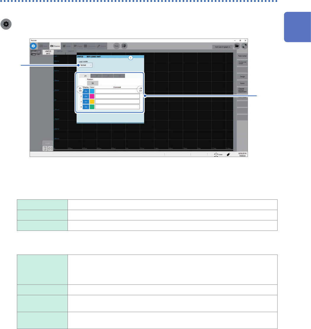
Logic channels
The logic sheet appears when the screen is in Single, Dual, Quad, Octa, or Hexadeca mode.
> [Channel]
1
2
1
Click the [Logic width] box, and then choose a display width for logic waveforms from the
list.
Making waveforms narrower can enhance the readability of a display that contains a large number of
waveforms.
This setting is a cross-module for all logic modules installed in the instrument.
Wide Increases the width of the waveforms.
Normal
Displays the waveforms in normal width.
Narrow Reduces the width of the waveforms.
2
Choose a display method for each probe (LA through LD).
Position Allows you to specify a numeral that represents a logic waveform position on the
screen in one percent point increments.
This setting is cross-probe for all probes (LA through LD).
You can freely move display positions of the logic waveforms on the display.
Display Allows you to choose whether to display logic waveform.
Color Allows you to choose a waveform display color. You can also choose the same color
as lines acquired across other channels.
Comment Allows you to type a comment for each channel.
Number of characters that can be entered: up to 40
1
Measurement Method