MR8740T_user_manual_eng_20191016H.pdf - 第48页
43 Fine-Adjusting Input V alues (V ernier Function) 3.3 Fine-Adjusting Input V alues (V ernier Function) Y ou can freely ne-adjust input voltage on the waveform screen. When recording physical values, such as noise, tem…
42
Converting Input Values (Scaling Function)
When using Model U8969 Strain Unit
When an inspection record of a strain gauge converter provides a calibration
factor
Example: To display data measured with the strain gauge converter having a calibration
factor of 0.001442 G/1 × 10
−6
strain* as values in terms of gravities (G)
(*: 10
−6
strain =
me
)
Scaling On (ENG)
Method Ratio
Units G
Ratio 0.001442 [G] (Displayed as “1.4420 m”)
When an inspection record of a strain gauge converter provides the rated
capacity and rated output
Refer to “When using the [Rating] setting” in “3.2 Converting Input Values (Scaling
Function)”(p. 41).
When using a strain gauge that has a gauge factor of other than 2.0
Model U8969 Strain Unit measures outputs of the gauge supposing that the gauge factor stands at
2.0.
When a strain gauge that has a gauge factor of other than 2.0 is used, you need to convert its
gauge factor into a conversion ratio.
For example, if the gauge factor stands at 2.1, the conversion ratio will be 0.952 (≈ 2 / 2.1).
Example: To display data measured with a strain gauge (gauge factor: 2.1) as values in terms
of gravities (G)
Two scaling (conversion ratio) calculations are required: a gauge ratio and conversion ratio that
converts output into physical quantities. In this case, enter the product of the conversion ratios of
the gauge factor and the scaling conversion ratio as the conversion ratio.
Where the conversion ratio of the gauge factor is 0.952, and the conversion ratio to convert data
into physical quantities is 0.001442*.
Conversion ratio = 0.952 × 0.001442 = 0.0013728
Enter [0.0013728] as the conversion ratio.
*: To convert values measured with a strain gauge into physical quantities, calculate the conversion ratio
based on Young’s modulus or Poisson’s ratio of a measuring object. The conversion method varies
depending on the conditions the strain gauge is used in.
Refer to “Scaling method for strain gauges” (p. 223).
43
Fine-Adjusting Input Values (Vernier Function)
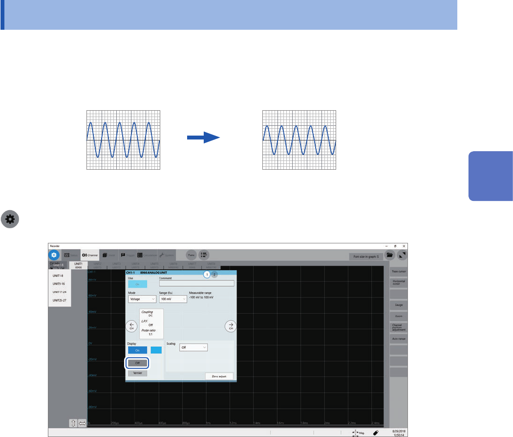
3.3 Fine-Adjusting Input Values (Vernier Function)
You can freely ne-adjust input voltage on the waveform screen. When recording physical values,
such as noise, temperature, and acceleration, with sensors, you can adjust those amplitudes, which
facilitates calibration.
Normal display Waveform processed by the vernier function
When an input voltage of 1.2 V is displayed
as a voltage of 1.0 V
1.0 V
1.2 V
> [Channel]
1
Click [Vernier].
The adjustment keypad appears.
2
While observing the waveform, you can ne-adjust its amplitude by clicking [−−], [−], [+],
and [++].
Click [C] to revert the ne-adjusted amplitude to its original.
• The adjustable range is from 50% to 200% of an original waveform.
• You cannot check if waveforms are adjusted by the vernier function by observing waveforms only.
• Waveform data (data saved as les) is that adjusted by the vernier function.
3
Advanced Functions
44
Inverting a Waveform (Invert Function)
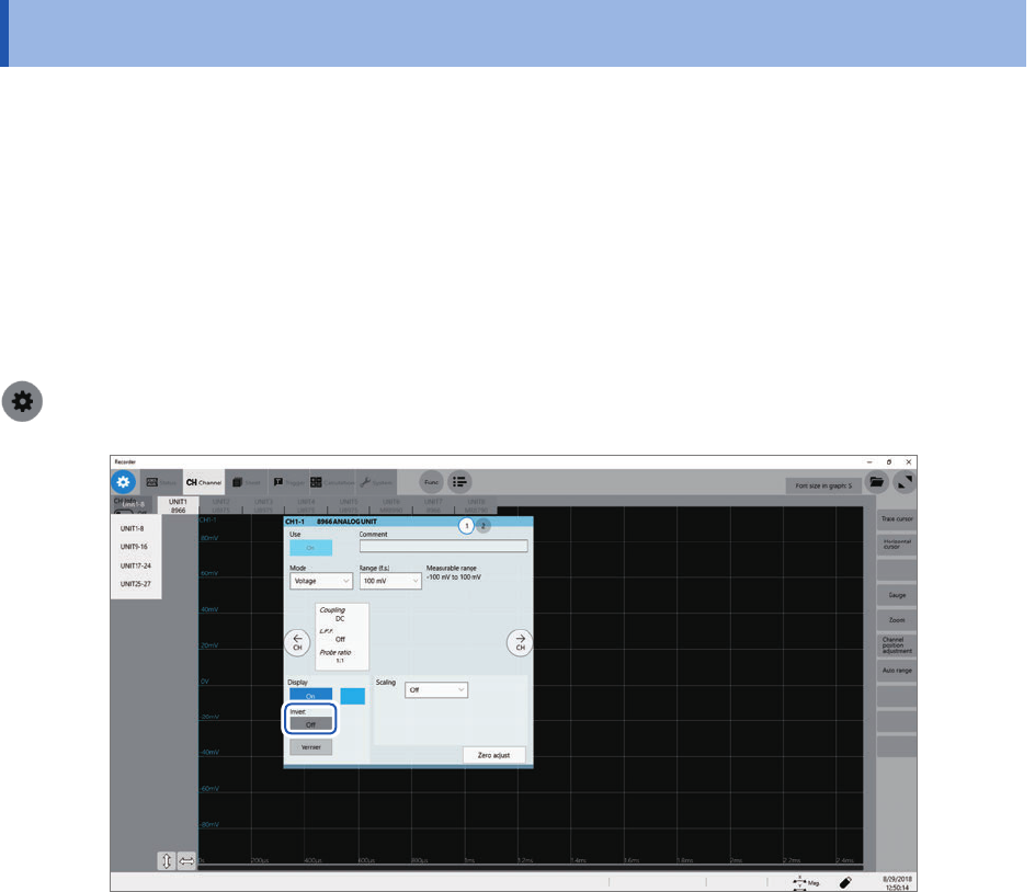
3.4 Inverting a Waveform (Invert Function)
You can invert a waveform relative to the X axis. This function can be used for analog channels
only.
Measured data saved in les is that inverted by the invert function.
Example:
• When a current sensor is clamped around a wire with its current direction mark mistakenly in the
direction opposite to the current ow
• When a signal is inputted with spring-pulling force negative and spring-compressing force
positive; however, you would like to display the results with spring-pulling force positive and
spring-compressing force negative
> [Channel]
Click the [Invert] button to set it to [On].
This setting is not available for Model 8967 Temp Unit, Model 8970 Freq Unit, and Model 8973
Logic Unit.