MR8740T_user_manual_eng_20191016H.pdf - 第58页
53 Conguring Measuring-Module-Specic Settings 9 Click the [Level] box, and then from the list, choose a side of the threshold level to be detected for pulse width measurement and duty ratio measurement. Only when [Mode…
52
Conguring Measuring-Module-Specic Settings
4
Click the [Threshold] box, and then enter a threshold value.
• Measured values are acquired based on the following: the interval between the subsequent two points
when measured waveform exceeds (or falls below) the threshold value, and the number of times when the
waveform exceeds (or falls below) the threshold value.
• The upper and lower limits of the threshold value and the increment in the threshold value vary depending
on the input voltage setting.
To prevent measurement errors due to noise, a hysteresis width of about 3% of the input voltage is tolerated
for the threshold.
(When [Input voltage] is set to [±10 V], it stands at about ±0.3 V.)
Specify a threshold allowing for tolerance that exceeds the hysteresis width relative to a peak voltage.
5
Click the [Slope] box, and then from the list, choose a signal direction to be detected.
Detects a waveform when it exceeds the specied threshold value (in the positive
direction).
Detects a waveform when it falls below the specied threshold value (in the negative
direction).
6
Click the [Division], and then enter a pulse count used for calculating frequency.
1
to 4,096
Example: For an encoder that outputs 360 pulses per rotation, set [Division] at [360] to measure a frequency
each rotation. When [Division] is not used, set it at [1].
7
Click the [Timing] box, and then from the list, choose a condition used for starting a count.
Only when [Mode] is set to [Count], this setting is available.
Start
Clicking the start icon starts accumulating.
Trigger Starts a count when the instrument is triggered.
• When [Timing] is set to [Start], some internal processing time is required between the time when the start
icon is clicked and the start of a measurement. Thus, the count value is not zero at the start point.
• When the [Timing] is set to [Start], an input that exceeds the trigger level does not trigger the instrument
while the instrument is lling the pre-trigger memory. Furthermore, the time for internal processing at the
start and the trigger priority setting may not cause the instrument to trigger even when the input signal
exceeds the specied trigger level.
• The memory division may cause the last data of the previous block to remain in the top of the block.
8
Click the [Count over] box, and then from the list, choose an action to be performed when a
count number is saturated.
Only when [Mode] is set to [Count], this setting is available.
Hold
Counts pulses and stops counting when the pulse count reaches the upper limit (65535
for the 40 k range).
Undo Starts counting pulses and brings the count back to zero when the pulse count reaches
25 times of the range gure (50000 for the 40 k range).

53
Conguring Measuring-Module-Specic Settings
9
Click the [Level] box, and then from the list, choose a side of the threshold level to be
detected for pulse width measurement and duty ratio measurement.
Only when [Mode] is set to [Pulse width] or [Duty ratio], this setting is available.
High
Measures waveforms on the upper side of the threshold level.
Low Measures waveforms on the lower side of the threshold level.
10
Click the [Smoothing] box, and then choose a scaling setting from the list.
Only when [Mode] is set to [Freq] or [Revolution], this setting is available.
Off
Records measured data without smoothing (resulting in a step-like waveform).
On Interpolates measured data to smooth a waveform and outputs it.
(Upper limit: 10 kHz; outputting data with this setting set to on lags behind that with this
setting set to off)
11
Click the [Hold] box, and then choose a measured-value retaining setting from the list.
Only when [Mode] is set to [Freq] or [Revolution], this setting is available.
Off (1 Hz),
Off (0.5 Hz),
Off (0.2 Hz),
Off (0.1 Hz)
When the instrument does not determine the measured value even after the frequency
reaches a value in the brackets, the measurement is dened to stop and regards the
measured value to be 0 Hz (0 rpm).
On
Retains the value conrmed the last time.
12
Click [Close].
The setting dialog box closes.
3
Advanced Functions
54
Conguring Measuring-Module-Specic Settings
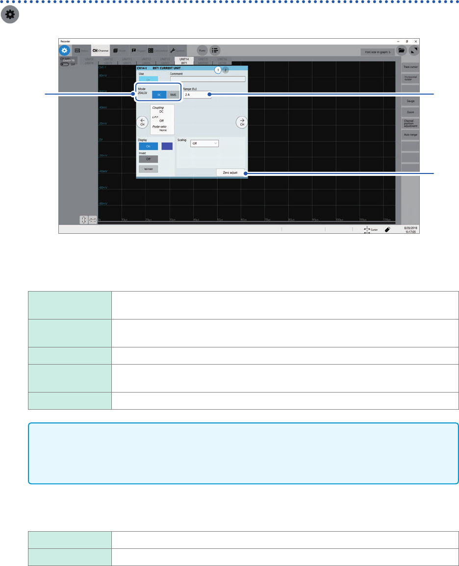
Conguring Model 8971 Current Unit settings
> [Channel] > [8971]
4
1, 2
3
1
Conrm the output rate displayed in the [Mode] area.
The instrument automatically recognizes a current sensor connected to Model 8971 Current Unit and displays
it as follows:
20A/2V When one of the following current sensors is connected: Model 9272-10 (20 A range)
and Model CT6841.
200A/2V When one of the following current sensors is connected: Model 9272-10 (200 A range),
Model CT6843, and CT6863.
50A/2V When Model CT6862 AC/DC Current Sensor is connected
500A/2V When one of the following current sensors is connected: Models 9709, CT6844,
CT6845, CT6846*, and CT6865*.
None When no current sensor is connected.
IMPORTANT
*: When Model CT6846 or Model CT6865 connects to Model 8971 Current Unit via Model 9318
Conversion Cable, the instrument recognizes the sensor as a 500 A AC/DC sensor. Set the
conversion ratio at 2.00 in the scaling setting to obtain correct current values.
2
In the [Mode] area, click the [DC] or [RMS] to choose a measurement mode.
DC
For current measurement
RMS For RMS measurement
3
(When you have changed the measurement mode) Click [Zero adjust].
The instrument performs zero-adjustment. Execute zero-adjustment without any input.