MR8740T_user_manual_eng_20191016H.pdf - 第74页
69 Conguring Generator-Module-Specic Settings Conguring Model MR8791 Pulse Generator Unit settings 1 Click [MR8791] . 6 1 3 4 5 2 2 Click the [Mode] box, and then choose an output type from the list. PULSE Outputs a…
68
Conguring Generator-Module-Specic Settings
Offset
Allows you to set an offset of the output sine wave.
Accuracy of the output voltage, which consists of amplitude and an offset value, is guaranteed in
the range of −10 V to +10 V.
An output waveform will appear with its upper parts limited to about +14 V and lower about −14 V
when the sum of the amplitude and offset value is set to out of the accuracy-guaranteed range.
−10.000 V to +10.000 V
4
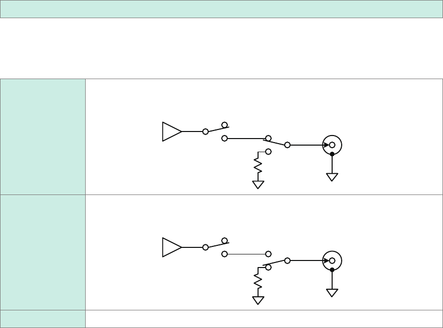
Choose whether to output a waveform.
Select a state at the time when no waveform is outputted
OFF (OPEN)
Does not output any waveform
Disconnect the output terminals from the internal circuit and short-circuits the terminal.
Internal
circuit
Output
terminal
OFF (SHORT)
Does not output any waveform
Disconnect the output terminals from the internal circuit and short-circuits the terminal.
Internal
circuit
About 20
Ω
Output
terminal
ON Outputs a waveform
5
Click [Send setting].
The instrument conrms the settings and outputs a waveform.
69
Conguring Generator-Module-Specic Settings
Conguring Model MR8791 Pulse Generator Unit settings
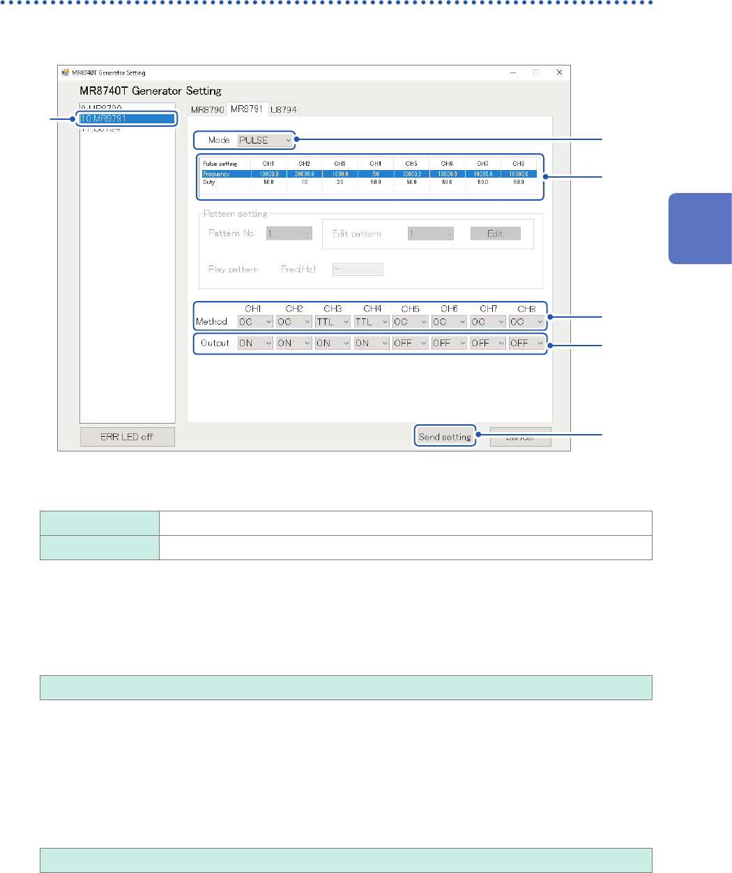
1
Click [MR8791].
6
1
3
4
5
2
2
Click the [Mode] box, and then choose an output type from the list.
PULSE
Outputs a pulse waveform.
PATTERN Outputs a pattern waveform.
3
Congure the pulse output settings.
Frequency
Allows you to enter a pulse output frequency. (In 0.1 Hz increments)
0.0 Hz to 20000.0 Hz
Duty ratio
Allows you to enter a pulse duty ratio. (In 0.1 percent point increments)
• With the 0% setting, the low-level signal is outputted; with the 100% setting, the high-level signal is
outputted. No pulse is outputted.
• With the 100% setting, the low-level signal is outputted even if the output setting is disabled.
• The output pulse width setting of 1 µs, which can be derived from the frequency and duty ratio settings, may
cause absence of pulses.
0.0% to 100.0%
3
Advanced Functions
70
Conguring Generator-Module-Specic Settings
4
Output conguration (Method)
You can congure the output settings.
The ground potential is cross-channel and not insulated.
With the open-collector output setting
• Limit the collector-emitter voltage to 50 V.
• Output signals require a response time of about 5 µs or less to rise from 10% to 90%. (With a load capacity
of 1000 pF and a pull-up resistamce of 1 k
Ω
, values for reference purposes)
TTL
TTL-level output (amplitude: 0-5 V)
OC Open-collector output
5
Output
Allows you to switch waveform output settings.
The instrument may momentary output a high-level signal at the times of power-on and power-off.
OFF
Does not output any waveform
ON Outputs a waveform
6
Conrmation of the setting
After nishing the setting, click
[Send setting]
.
The instrument conrms the settings and outputs a waveform.
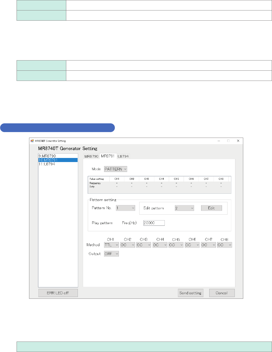
Conguring the pattern output settings
Pattern number
Enter an pattern number.
• When no output is enabled, the instrument outputs the pattern signal registered rst.
• Turning off the instrument clears pattern data sets. After turning on the instrument, re-register pattern data
set.
1 to 16