3OM-996-005.pdf - 第109页
1.0 1.0 1.0 1.0 1.0 1.0 1.0 1.0 Y X (4) Specifications of Lines extended from a Pad Mark or a Through Hole Unit: mm Fig. 3B69 (a) A through hole or a pad mark should have only one land which is directed in increments of …
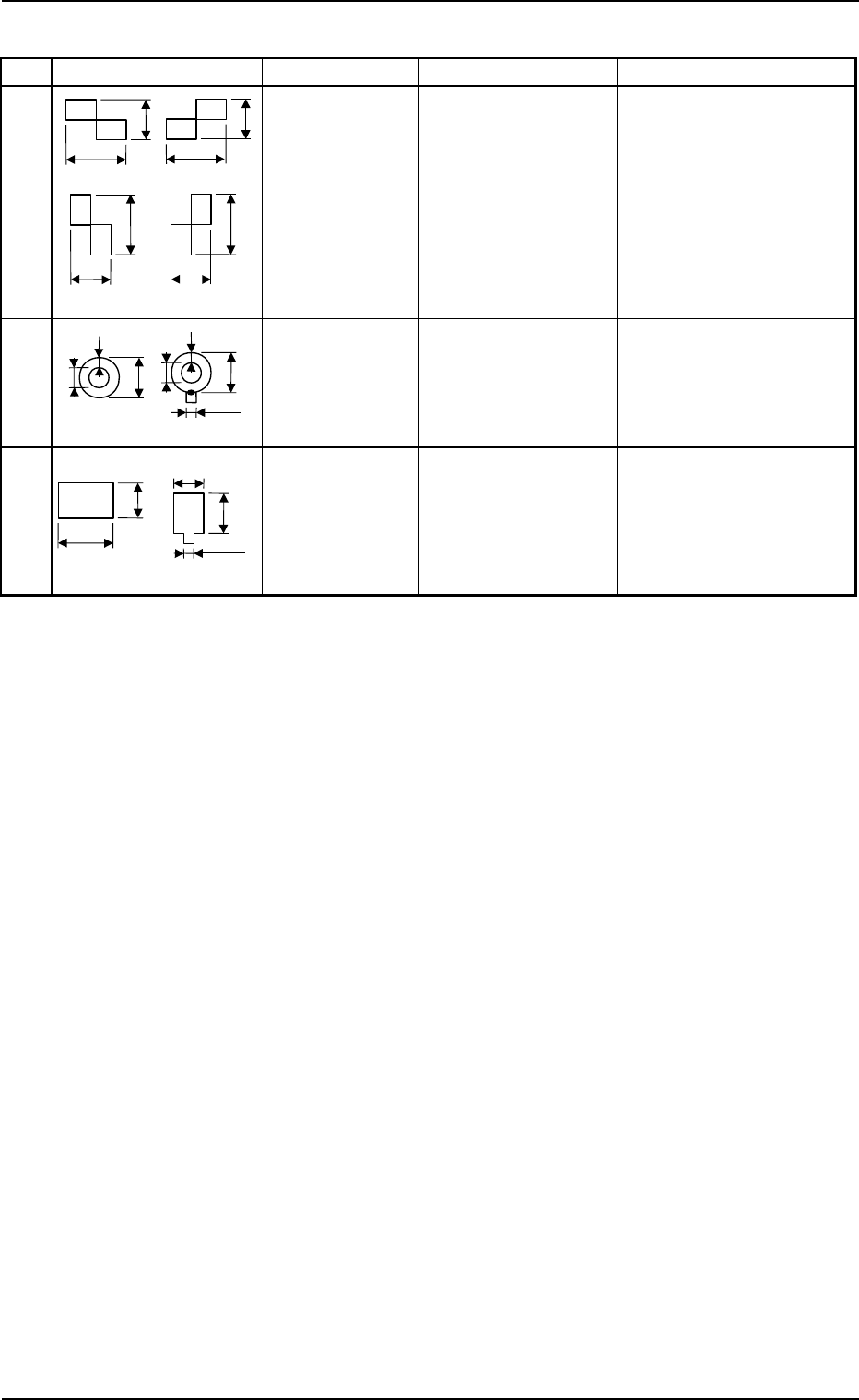
Table 3B17
Mark Type D1 (Unit: mm) D2 (Unit: mm) Remarks
0.5 to 3.0 (±10%) 0.5 to 3.0 (±10%) • Mark Reference:
Contact of Two Rect-
angles
1.0 to 2.0 (±10%) 0.5 to 1.5 (±10%) • Mark Reference: Center
• D2: Diameter of Punched
Hole
• W : Min. 0.25 mm
0.5 to 2.0 (±10%) 0.5 to 2.0 (±10%) • Mark Reference:
Center of Gravity
(2) Material for Marks
Copper Leaf (Au and Ni plating possible but mirror surface cannot be used.)
Solder-Plated Marks (Consult our marketing department or sales agency for
details.)
Solder Leveler (Consult our marketing department or sales agency for de-
tails.)
(3) Material for P.C.B.
Glass Epoxy (Consult our marketing department for hypochromic one.)
Ceramic (Consult our marketing department for details.)
(Front Side of Machine)
(Note a)
D1
D2
D2
W
W
D1
(Front Side of Machine)
D2
D2
D1
D1
(Note a)
2.3 Operation Data
0305-001 2-39 AIM01EDTP
Checker (Rectangle)
Thru Hole
(Round)
Pad Mark
(Rectangle)
D1
D1
D1
D1
D2
D2
D2
D2
or
or
(Front Side of Machine)
1.0
1.0
1.0
1.0
1.0
1.0
1.0
1.0
Y
X
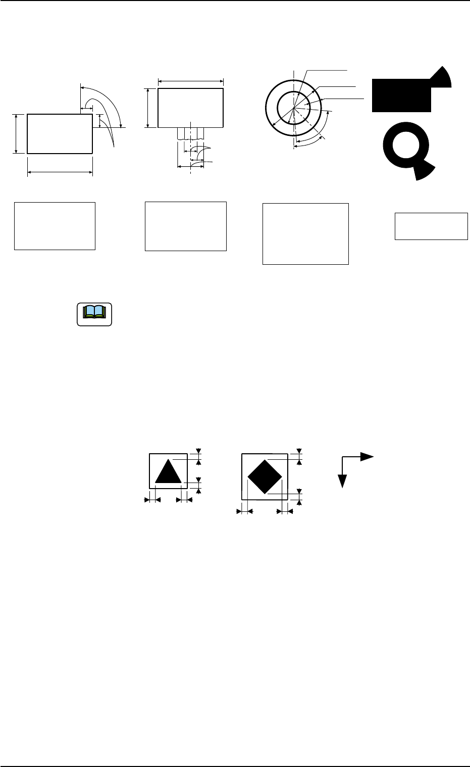
(4) Specifications of Lines extended from a Pad Mark or a Through Hole
Unit: mm
Fig. 3B69
(a) A through hole or a pad mark should have only one land
which is directed in increments of 45°.
Consult our marketing department or sales agency for de-
tails such as dimensions, etc.
(b) A copper leaf, a resist, a coating, a silk print, and a
punched hole should not exist in the range of 1.0 mm in
both X and Y directions from the outermost edges of a
fiducial mark. They may cause false recognition.
Example:
(Front Side of Machine) Unit: mm
Fig. 3B70
(c) The shape of P.C.B. (a cutout, a punched hole), the exter-
nal elements (light reflected from a structure, light emitted
from an external device, etc.) may sometimes interfere with
recognition of the fiducial marks. Consult our marketing
department or salses agency for details.
(d) A fiducial mark should make ample contrast with the sur-
roundings. (To prevent false recognition)
(e) Anything resembling a pattern similar to a fiducial mark
should not exist in the designated window. If one exists, it
may cause false recognition.
(f) A test may be required when the fiducial mark cannot be
recognized because of the extreme warpage of the P.C.B.
2.3 Operation Data
0305-001 2-40 AIM01EDTP
Note
Range of Tangent
Lines related between
Pad Mark and Land
Range of Land
Location in
Increments of 45°
for Pad Mark
Range of Land
Location in
Increments of 90°
for Pad Mark
(Front Side of Machine)
1/3 of Shorter Side
0.5 to 2.0
0.5 to 2.0
Examples of
Land Locations
Range of Land
Location for
Through Hole
(45° at the bottom
right of the hole)
0.5 to 1.5
1.0 to 2.0
Min.0.25
45°
80°
0.5 to 2.0
0.5 to 2.0
(Front Side of Machine)
(Front Side of Machine)
(Front Side of Machine)
1/3 of Shorter Side
Range of Tangent
Lines related between
Pad Mark and Land
Range of Tangent
Lines related between
Pad Mark and Land
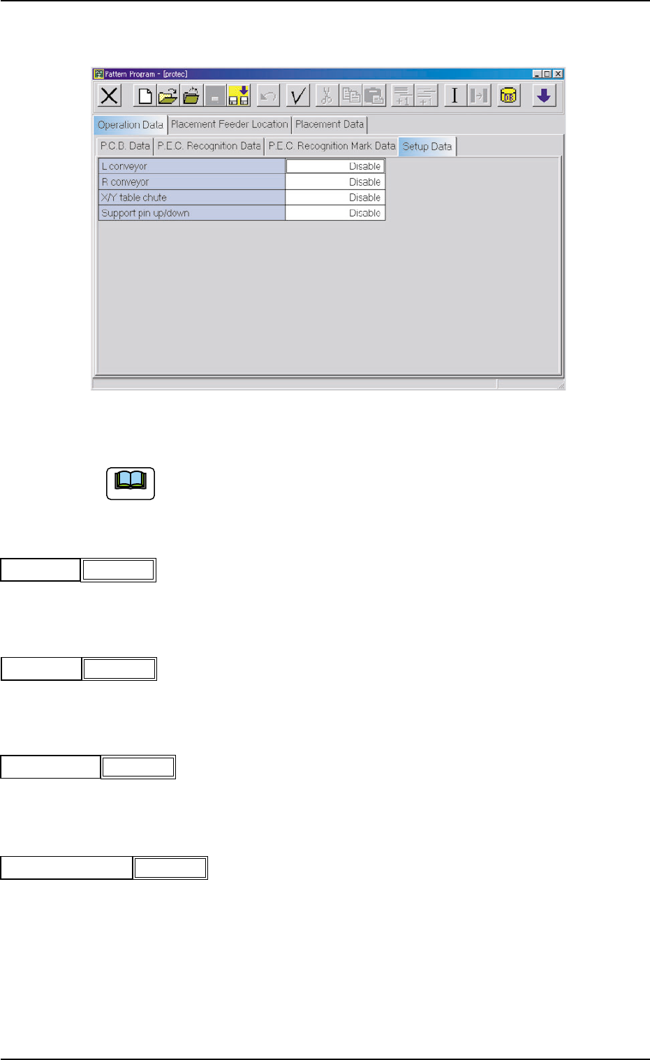
(A04) Setup Data
Fig. 3B71 Edit Window (Example)
Unless "Enable" is selected for a device to be set up, the machine does
not perform any setup operation on the device.
(A04_01) L conveyor
Set "Disable" or "Enable" in the text box.
(A04_02) R conveyor
Set "Disable" or "Enable" in the text box.
(A04_03) X/Y table chute
Set "Disable" or "Enable" in the text box.
(A04_04) Support pin up/down
Set "Disable" or "Enable" in the text box.
Note
2.3 Operation Data
0305-001 2-41 AIM01EDTP
Disable
L conveyor
Fig. 3B72
R conveyor
Fig. 3B73
Disable
X/Y table chute
Fig. 3B74
Disable
Support pin up/down
Fig. 3B75
Disable