3OM-996-005.pdf - 第216页
*5 Lighting pattern Back ltg, Front ltg 1 (Ring), Front ltg 2 (Coax) When "Manual" is set in the "Lighting pattern" text box, it is re- quired to enter parameters in these text boxes. *7 Mold size tol…
3.3 "Recognition Data" Tab
• Sheet Layout
When the "Recognition Data" tab is pressed, the "Recognition Data"
tab sheet appears.
The "Recognition Data" tab sheet can be classified by shapes and
divided into two kinds as follows.
• Cylindrical, Square, Deform (Simple)
• IC (Simple), Other Leaded (Simple), Connector (Simple)
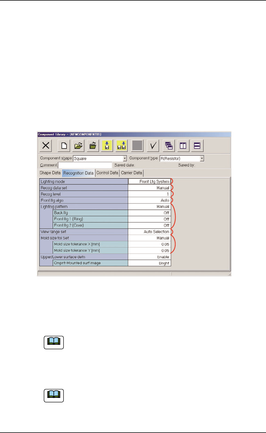
3.3.1 Cylindrical, Square, and Deform (Simple)
Fig. 3C18 "Recognition Data" Tab Sheet ("Square" Selected)
• Sheet Composition
Each parameter is displayed or can be entered.
Refer to "4.1.3 Basic Usage of Text Boxes" (Section 2) for the
detailed information on how to enter each parameter.
*1 Lighting mode, *2 Recog data set, *3 Recog level,
*4 Back ltg algo (Front ltg algo), *6 View range Set
"Back ltg algo" or "Front ltg algo" appears in "*4", depending on
which lighting mode is selected in the "Lighting mode" text box.
3.3 "Recognition Data" Tab
*1
*2
*3
*4
*5
*6
*7
0510-002 3-28 AIM01EDTP
Note
Note
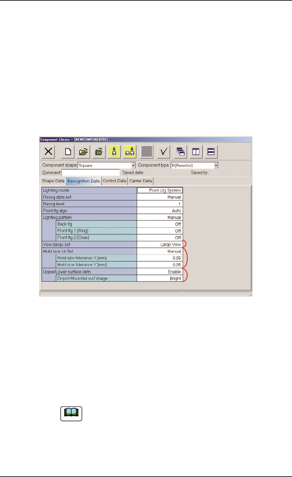
*5 Lighting pattern
Back ltg, Front ltg 1 (Ring), Front ltg 2 (Coax)
When "Manual" is set in the "Lighting pattern" text box, it is re-
quired to enter parameters in these text boxes.
*7 Mold size tol Set
Mold size tolerance X [mm] (Horizontal), Mold size toler-
ance Y [mm] (Vertical)
When "Manual" is set in the "Mold size tol Set" text box, it is re-
quired to enter parameters in these text boxes.
Fig. 3C19
*8 Upper/Lower surface detn
When the "Front Ltg System" is set in the "Lighting system" text
box (*1), it is required to enter a parameter in the text box.
Cmpnt-Mounted surf image
When "Enable" is set in the "Upper/Lower surface detn", it is re-
quired to enter a parameter in the text box.
When a component shape other than "Square" is selected
in the "Component shape" combo box, "Upper/Lower sur-
face detn" is not displayed.
The upper/lower surface detection function can be used
when the component shape is "Square" and the pickup
surface appears black.
0510-002 3-29
AIM01EDTP
3.3 "Recognition Data" Tab
*6
*7
*8
Note
0510-002 3-30 AIM01EDTP
3.3 "Recognition Data" Tab
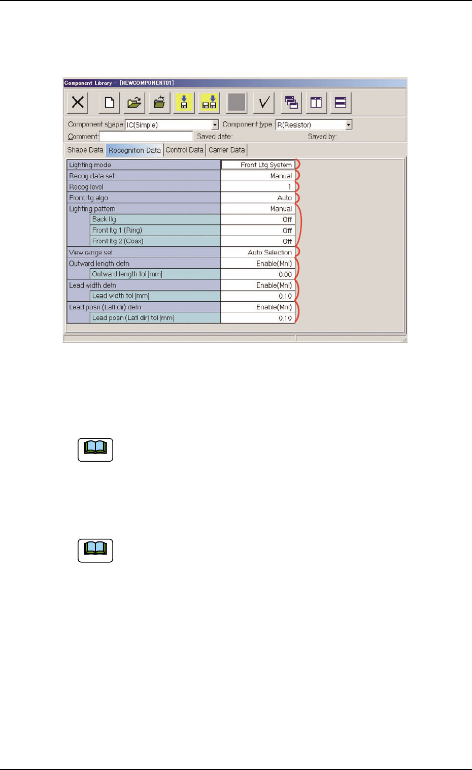
3.3.2 IC (Simple), IC (Complex), Other Leaded (Simple),
Other Leaded (Complex), Connector (Simple),
Connector (Complex)
Fig. 3C20 "Recognition Data" Tab Sheet ("IC (Simple)" Selected)
• Sheet Composition
Each parameter is displayed or can be entered.
Refer to "4.1.3 Basic Usage of Text Boxes" for the detailed in-
formation on how to enter each parameter.
*1 Lighting mode, *2 Recog data set, *3 Recog level,
*4 Back ltg algo (Front ltg algo), *6 View range set
"Back ltg algo" or "Front ltg algo" appears in "*4", depending on
which lighting mode is selected in the "Lighting mode" text box.
*5 Lighting pattern
Back ltg, Front ltg 1 (Ring), Front ltg 2 (Coax)
When "Manual" is set in the "Lighting pattern" text box, it is re-
quired to enter parameters in these text boxes.
Note
Note
*5
*1
*2
*6
*7
*3
*4
*8
*9