3OM-996-005.pdf - 第335页
0510-001 5-47-5 AIM01EDTP 3.3 "Auto Operation" T ab • Example of "Sampling Bias" Mode = Sampling Bias, Bias coefficient (X) [%] = 50, Bias coefficient (Y) [%] = 50 First Follow-Up after Component Repl…
Second Follow-Up after Component Replacement
Components are picked up and recognized based on the first
corrected value as frequently as the specified number of picks.
Mean of Deviations as Results of 3-time Recognitions ×
70% (50% + 40%/2) = Calculation of Second Corrected Value
This "Second Corrected Value" is also reflected on the pickup
motions taken subsequently after "Next" in the figure.
(The third and subsequent follow-ups are the same as "Stan-
dard".)
The amount of feedback is saved in Reel Offset B.
1
2
3
Next
Fig. 3E44-2
Note
0510-001 5-47-4 AIM01EDTP
3.3 "Auto Operation" Tab
0510-001 5-47-5 AIM01EDTP
3.3 "Auto Operation" Tab
• Example of "Sampling Bias"
Mode = Sampling Bias, Bias coefficient (X) [%] = 50,
Bias coefficient (Y) [%] = 50
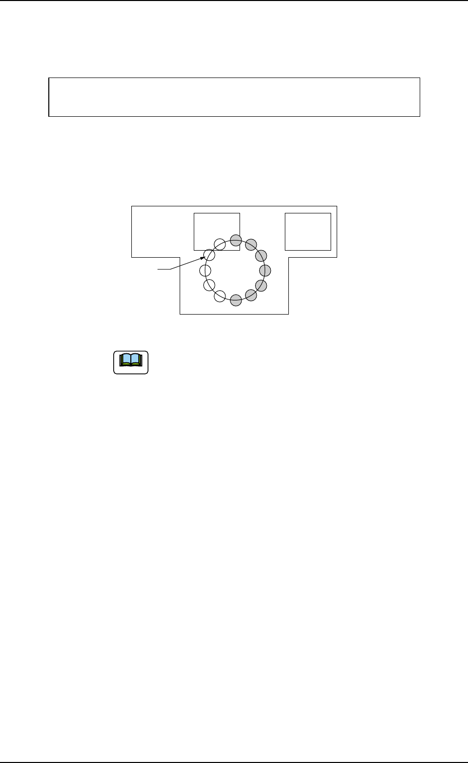
First Follow-Up after Component Replacement
The deviation is measured based on the first (= sample) compo-
nent recognition that was performed when a component was
picked up after component replacement.
Deviation as Result of 1-time Recognition ×
90% (50% + 40%) = Calculation of First Corrected Value
This "First Corrected Value" is reflected on the pickup motions
taken subsequently after "Next" in the figure.
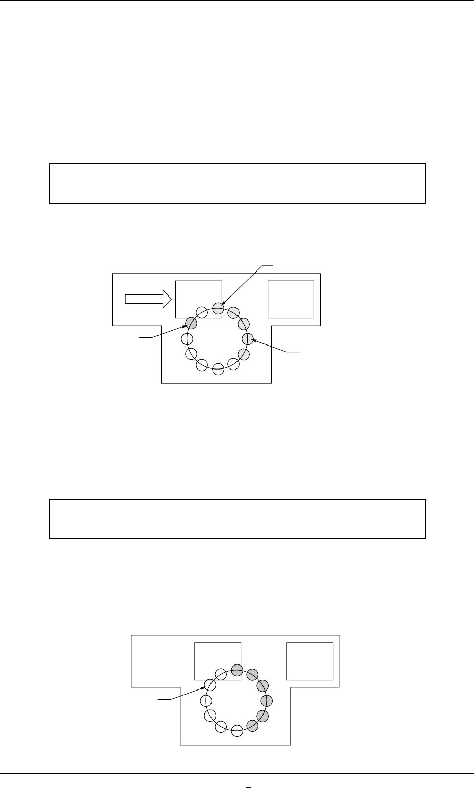
Second Follow-Up after Component Replacement
The deviations are measured based on the component recogni-
tions that were performed twice (the number of component picks)
with the first corrected value.
Mean of Deviations as Results of 2-time Recognitions ×
70% (50% + 40%/2) = Calculation of Second Corrected Value
This "Second Corrected Value" is also reflected on the pickup
motions taken subsequently after "Next" in the figure.
(The third and subsequent follow-ups are the same as "Stan-
dard".)
1
Next
Fig. 3E44-3
Component
Recognition
Component Pickup
1
2
Next
Fig. 3E44-4

0305-001 5-48 AIM01EDTP
*5 Feeder message rate
Error counts [times], # of picks [times]
Set the parameters to show the feeder slot No. (Fdr. No.) of the
tape feeder whose pickup rate has deteriorated during automatic
operation.
When the number of picks has reached the specified value, the
parameter in the "Error counts [times]" text box is cleared.
When the number of pickup errors has reached the specified error
counts before the number of picks reaches the specified number of
picks, a warning message is issued as machine information.
(a) The number of picks and pickup errors is managed
for each feeder slot No. but the parameters in the "Er-
ror counts [times]" and "# of picks [times]" text boxes
are equally reflected on every feeder slot No.
(b) The data input range is "0 to 9999" (times) for both
"Error counts [times]" and "# of picks [times]".
(c) When "0" (zero) is set for "# of picks [times]" and "Er-
ror counts [times]" or the parameter in the "Error counts
[times]" text box is larger than the parameter in the "#
of picks [times]" text box, no warning message is is-
sued.
3.3 "Auto Operation" Tab
Note