3OM-996-005.pdf - 第114页
2 .5 Placement Data Fig. 3B85 Edit Window (Example) (C01) Placement Data Un (C01_01) Placement Data Unit Designation Select one of the following tabs (placement data groups) in one pattern program. U 0 1 : First Placemen…

(B01_06) Feeder Fixed
Select "Enable" or "Disable" to determine whether or not the feeder
positions should be fixed in place.
When "Enable" is selected, the feeder No. (Fdr No.) and the compo-
nent ID are not affected by any insert and delete operations of a com-
ponent.
Disable : The feeder position is not fixed.
Enable : The feeder position is fixed.
(B01_07) Feeder Alternate
Select "Enable" or "Disable" to determine whether or not the feeder
alternate function should be used.
Disable : The feeder alternate function is not used.
Enable : The feeder alternate function is used.
(B01_08) Fdr No.
When "Enable" is selected for the feeder alternate function, set the
destination feeder No. (Fdr No.) of the feeder that will work in place of
the feeder where a component shortage error has occurred.
2.4 Placement Feeder Location Data
0404-002 2-44 AIM01EDTP
Feeder Alternate
Fig. 3B83
Disable
000 (000)Fdr No.
Fig. 3B84
Feeder Fixed
Fig. 3B82
Disable
2.5 Placement Data
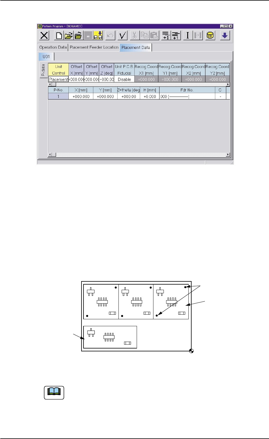
Fig. 3B85 Edit Window (Example)
(C01) Placement Data Un
(C01_01) Placement Data Unit Designation
Select one of the following tabs (placement data groups) in
one pattern program.
U01 : First Placement Data Group
U02 : Second Placement Data Group
↓
Un : Up to 99 placement data groups can be specified.
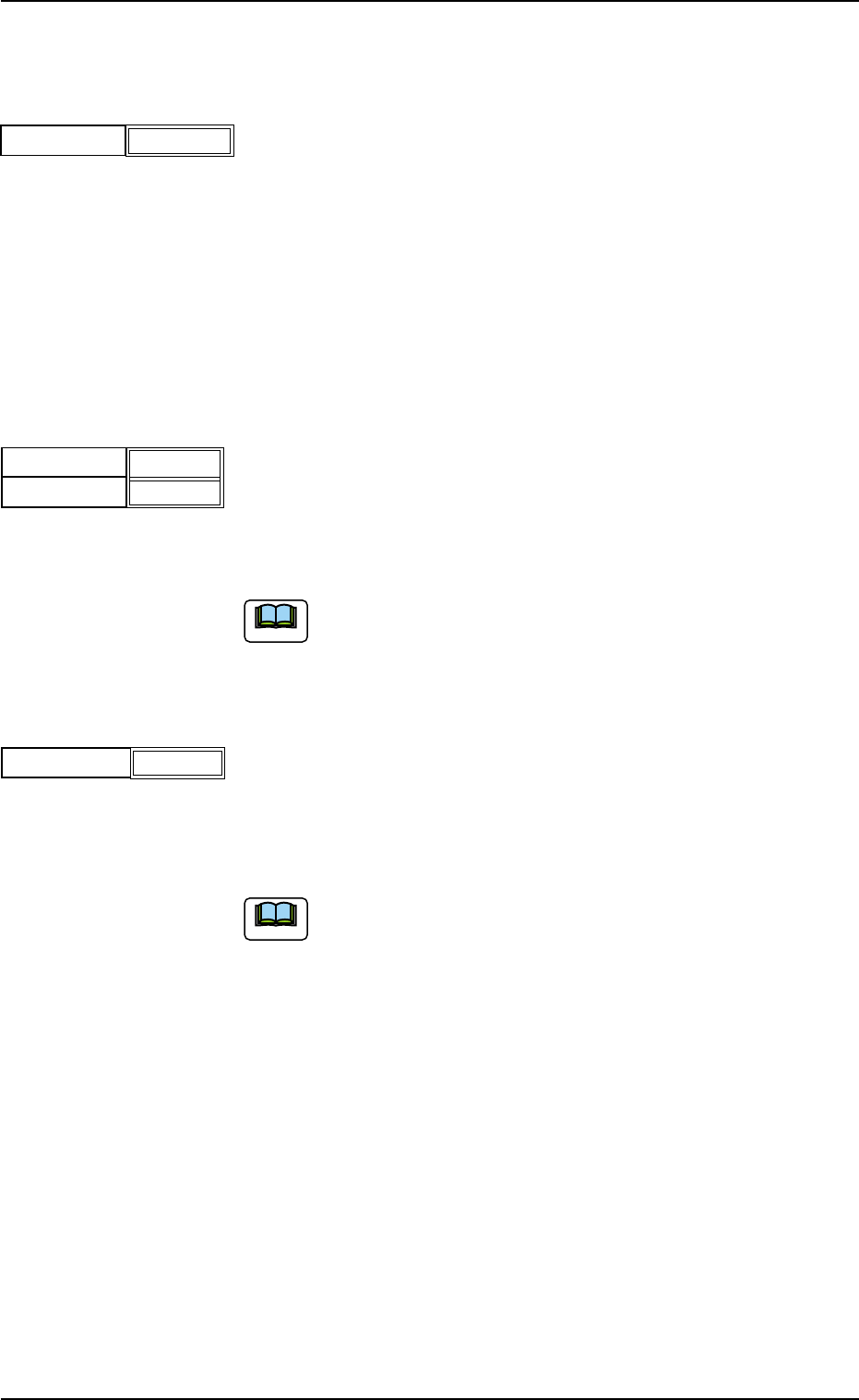
Fig. 3B86 Example of Placement Data (TCM-X210)
(a) "U01" is used in normal cases.
(b) The operation and feeder location data are used commonly.
(c) Refer to "2.1Types of P.C.B.’s and Required Data" and "Exemplified
Data Creation" for details.
(d) The placement coordinate reference of TCM-X110 is "Rear Left".
U02
U01
Fiducial Marks
Placement Coordinate Reference Point
Note
2.5 Placement Data
0305-001 2-45 AIM01EDTP
(C02) Placement Data (P-data)
(C02_01) Unit Control
Select one of the following options to determine whether the selected
placement data (U01, U02, ..... Un) should be used.
In normal cases, select "Placement".
Placement : The placement data of the selected unit (group) be-
comes valid.
Bypass : The placement data of the selected unit (group) be-
comes invalid.
Offset X [mm] and Offset Y [mm]
Set the offset values for all placement coordinates X and Y and the
recognition coordinates of the unit P.C.B. in the placement data (P-
data).
Unit: mm
(a) Use "000.000" (zero) in normal cases.
(b) Note that these offset values do not give any effect to the
coordinates (X [mm] and Y [mm]) of "(A02_02) P.E.C.
recognition mode global".
Offset Z [deg]
Set the offset value for all placement angles (Z=Theta) in the place-
ment data (P-data).
Unit: °(degree)
Use "000.00" (zero) in normal cases.
Note
Note
2.5 Placement Data
0305-001 2-46 AIM01EDTP
Placement
Unit Control
Fig. 3B87
Fig. 3B88
Offset X [mm]
Offset Y [mm]
+000.000
+000.000
Fig. 3B89
+000.00
Offset Z [deg]