3OM-996-005.pdf - 第317页
(4) "Nozzle-L" and "Nozzle-H" T abs Follow the same procedure for the "Nozzle-H" tab sheet. • Sheet Layout When the "Nozzle-L" tab is pressed in the "Nozzle" tab sheet, t…
(3) "Nozzle Position" Tab
• Sheet Layout
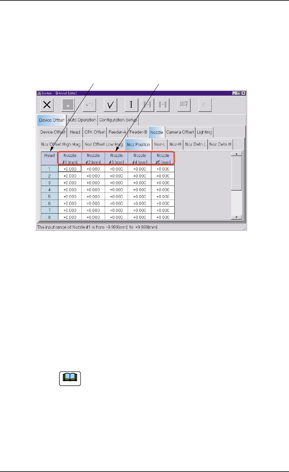
When the "Nozzle Position" tab is pressed in the "Nozzle" tab sheet, the
following tab sheet appears.
Fig. 3E32 "Nozzle Position" Tab Sheet
• Sheet Composition
*1 Head
The head Nos. are displayed.
*2 Nozzle #1 [mm], Nozzle #2 [mm], Nozzle #3 [mm], Nozzle #4
[mm], Nozzle #5 [mm]
Each text box shows an offset value that is used to manage the
distance (rotation radius) between the head rotational center and
each nozzle.
(a) These parameters are used to calculate the track of
nozzle rotation for pickup position correction.
Plus or minus values are allocated on the basis of the
design value (R = 7.500 mm).
(b) These offset parameters are automatically calculated
through teaching operation.
0403-002 5-34
AIM01EDTP
*1
*2
Note
3.2 "Device Offset" Tab
(4) "Nozzle-L" and "Nozzle-H" Tabs
Follow the same procedure for the "Nozzle-H" tab sheet.
• Sheet Layout
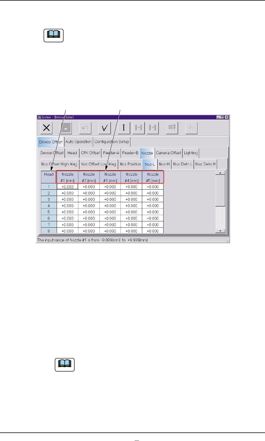
When the "Nozzle-L" tab is pressed in the "Nozzle" tab sheet, the fol-
lowing tab sheet appears. When the "Nozzle-H" tab is pressed, almost
the same tab sheet appears.
Fig. 3E33 "Nozzle-L" Tab Sheet
• Sheet Composition
*1 Head
The head Nos. are displayed.
*2 Nozzle #1 [mm], Nozzle #2 [mm], Nozzle #3 [mm], Nozzle #4
[mm], Nozzle #5 [mm]
Each text box shows an offset value that is used to correct varia-
tions in each nozzle height when the nozzle U/D selector (L/H se-
lection) is set to "L" (Low Level) or "H" (High Level).
(a) A plus or minus value is allocated according to the level
variation of each nozzle compared with the origin of
the linear measure detection sensor.
(b) When a nozzle is located above the origin level of
the linear measure detection sensor, a minus (-)
value must be entered as the offset data.
0403-002 5-35 AIM01EDTP
*1 *2
3.2 "Device Offset" Tab
Note
Note
0403-001 5-35-1 AIM01EDTP
3.2 "Device Offset" Tab
(5) "Noz Detn L" and "Noz Detn H" Tabs
The navigations similar to those through the "Noz Detn L" tab
sheet can be followed through the "Noz Detn H" tab sheet.
• Sheet Layout
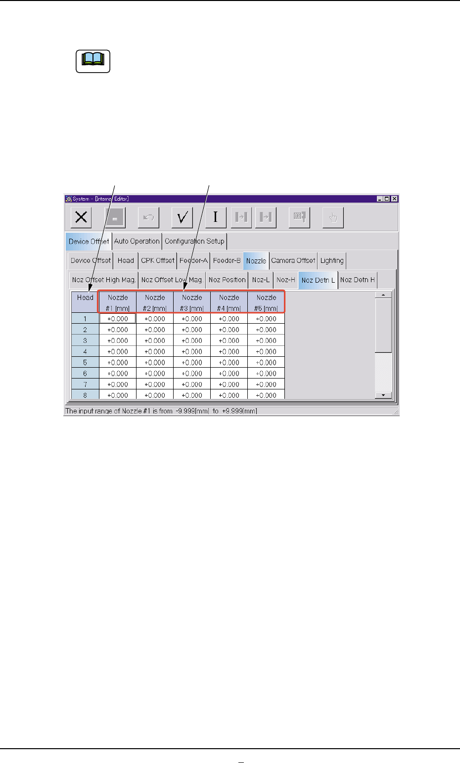
When the "Noz Detn L" or the "Noz Detn H" tab in the "Nozzle" tab
sheet is selected, the following tab sheet (Nozzle Detection L) appears.
Fig. 3E33-1
• Sheet Composition
*1 Head
The head Nos. are displayed.
*2 Nozzle #1 [mm], Nozzle #2 [mm], Nozzle #3 [mm], Nozzle #4
[mm], Nozzle #5 [mm]
Shown is the offset data of each nozzle level for "(L)" and "(H)" in
the component backtrack detection.
Note
*1 *2