3OM-996-005.pdf - 第351页
*18 T ransfer conveyor reverse speed When a P .C.B. is transferred, the rotation of the conveyor is re- versed to bring the P .C.B. close to the transfer claw . The speed of the reverse rotation can be specified in this …

0305-001 5-62 AIM01EDTP
*13 P.C.B. clamp timer [sec]
Set the P.C.B. clamp timer in the text box.
*14 Pass mode select
One of the following options can be selected as a way to pass a
P.C.B.
Conveyor : The conveyor is activated to pass a P.C.B.
Transfer claw : The conveyor and the P.C.B. transfer claw are
activated to pass a P.C.B.
*15 Output Conveyor P.C.B. Out
Set "Disable" or "Enable" in the text box to determine whether or
not a disengaged P.C.B. should be detected in the output conveyor
section.
*16 Furnace Signal Check
Set "Disable" or "Enable" in the text box to determine whether or
not the furnace signal check function should be used.
When "SMEMA" is set in the "Input mode" or the "Output
mode" text box, this function does not work.
*17 P.C.B. exist signal check
It must be determined whether or not the P.C.B. exist signal should
be checked.
No Check : The P.C.B. exist signal is not checked.
Input & Output : The P.C.B. exist signals from the input/output
machines are checked.
Input : Only the P.C.B. exist signal from the input ma-
chine is checked.
Output : Only the P.C.B. exist signal from the output ma-
chine is checked.
(a) When a parameter other than "No Check" is set in the
"P.C.B. exist signal check" text box, the P.C.B.’s on
the conveyors of the input and output machines are
detected and the automatic setup actions, etc., are
restricted.
(b) When "SMEMA" is set in the "Input mode" or the "Out-
put mode" text box, this function does not work.
3.3 "Auto Operation" Tab
Note
Note

*18 Transfer conveyor reverse speed
When a P.C.B. is transferred, the rotation of the conveyor is re-
versed to bring the P.C.B. close to the transfer claw. The speed of
the reverse rotation can be specified in this text box.
Select one of the following options.
Full Speed, 10%Decr, 20%Decr, 30%Decr, 40%Decr,
50%Decr, 60%Decr, 70%Decr, 80%Decr, 90%Decr
0305-001 5-63
AIM01EDTP
3.3 "Auto Operation" Tab
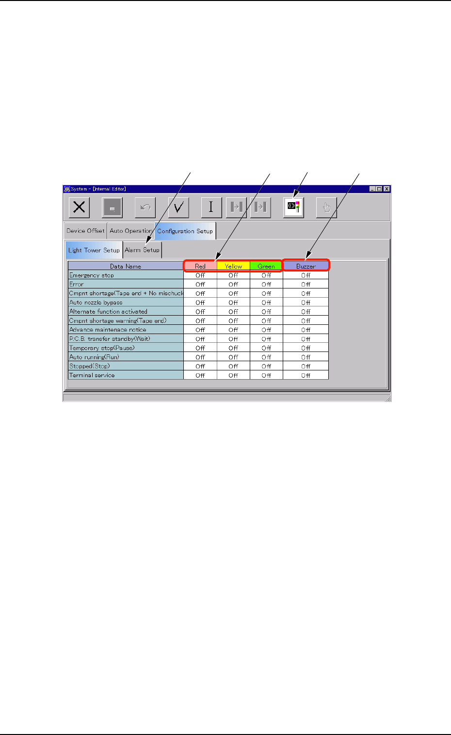
3.4 "Configuration Setup" Tab
3.4.1 "Light Tower Setup" Tab
• Sheet Layout
When the "Light Tower Setup" tab is pressed in the "Configuration Setup"
tab sheet, the following tab sheet appears.
Fig. 3E54 "Light Tower Setup" Tab Sheet
• Sheet Composition
*1 Data Name
Displayed are the items for which the colors (red, yellow, and green)
of the tower lights and the types of alarm sounds should be speci-
fied.
*2 Red, Yellow, Green
Set "On", "On & Off", or "Off" in each text box to specify the colors
(red, yellow, and green) of the tower lights.
*3 Buzzer
Set "Off", "Intmt Snd", "Cont Snd", or "Optl Snd" in each text box to
specify the types of alarm sounds.
The desired sound patterns can be made, using the "Alarm Setup"
tab sheet.
0305-001 5-64
AIM01EDTP
3.4 "Configuration Setup" Tab
*1
*2
*3
*4