3OM-996-005.pdf - 第178页
4 .4 "Placement Data" T ab The "Placement Data" tab is provided with [U01 to Un] tabs and [P-data] and [O-data] tabs. When a tab is selected, the corresponding tab sheet appears. 4.4.1 "U01"…
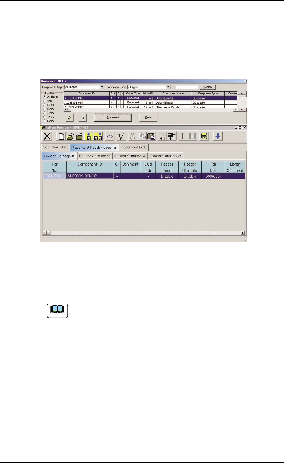
Allocation of Component ID
(1) Select the "Feeder Carriage #" tab where a component ID should
be allocated.
(2) Select the feeder No. (Fdr. No.) where a component ID should be
allocated.
The selected line (Fdr. No.) turns blue, indicating that it is selected.
Fig. 3B168
(3) Select the desired component ID to be allocated in the "Component
ID List" window.
Select the desired options from the "Component Shape" and
"Component Type" drop-down lists and the desired radio button
in the "Fdr Width" group box to determine the properties of the
component ID as the requirements to be fulfilled.
(4) Press the [Placement] button.
The selected component ID is allocated to the "Fdr No." line that
has turned blue.
Deletion of Allocated Component ID
(1) Select the desired "Feeder Carriage #" tab and the feeder No. (Fdr
No.) of the component to be deleted.
The selected line (Fdr. No.) turns blue, indicating that it is selected.
(2) Select the "Cut" icon on the toolbar. The selected feeder No. (Fdr
No.) is deleted and the subsequent feeder Nos. are shifted up.
0510-002 2-106
AIM01EDTP
4.3 "Placement Feeder Location" Tab
Note
4.4 "Placement Data" Tab
The "Placement Data" tab is provided with [U01 to Un] tabs and [P-data]
and [O-data] tabs. When a tab is selected, the corresponding tab sheet
appears.
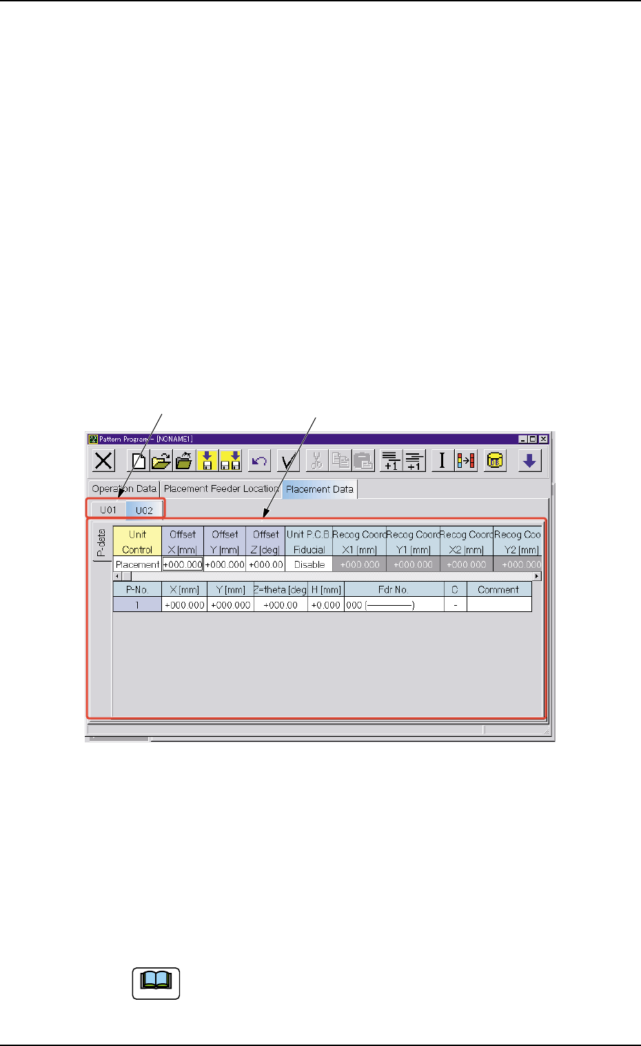
4.4.1 "U01" to "Un" Tabs
[U01] represents [Unit No. 01] and [n] in [Un] can be any number (01, 02,
03, ...). When the [Un] tab is pressed, the corresponding tab sheet ap-
pears, enabling you to edit the parameters (placement data) of the se-
lected unit.
• Sheet Layout
When the "U01" tab is pressed after the "Placement Data" tab is
selected, the following tab sheet appears.
Fig. 3B169 "U01" Tab Sheet
• Sheet Composition
Each parameter is displayed or can be entered.
*1 [U01] to [Un] Tabs
These tabs are used to select a unit. When a tab is pressed, the
corresponding tab sheet appears and is related to the selected unit.
Refer to "• Operation Procedure" (described later) for the
detailed information on how to add or delete a unit.
Note
*1 *2
0305-001 2-107 AIM01EDTP
4.4 "Placement Data" Tab
*2 "Placement Data" Edit Windows
These windows can be used to edit the placement data (P) and (O).
Refer to "4.4.2 "P-data" Tab" and "4.4.3 "O-data" Tab" for
details.
• Operation Procedure
Addition of New Unit
(1) When the second toolbar is not visible, press the [Open 2nd.
Toolbar] icon [ ] to make the second toolbar visible.
(2) When the [Add U Data] icon (
) is selected, a new unit is added
to the last line.
Deletion of Unit
(1) When the second toolbar is not visible, press the [Open 2nd.
Toolbar] icon [
] to make the second toolbar visible.
(2) Use the touch screen or the pointing device to select the unit to
be deleted.
(3) When the [Delete U Data] icon (
) is selected, the selected unit
is deleted.
When a tab (unit) between the adjacent ones is deleted,
the subsequent tabs (units) are shifted left.
Unit Copy and Paste Commands
(1) When the second toolbar is not visible, press the [Open 2nd.
Toolbar] icon [ ] to make the second toolbar visible.
(2) Use the touch screen or the pointing device to select the unit to
be copied.
(3) When the [Copy U Data] icon [
] is selected, the selected unit
is copied.
(4) Select the position of the tab (unit) to be pasted.
(5) When the [Paste U Data] icon [
] is selected, the selected unit
is pasted.
The toolbar is also provided with the [Cut U Data] icon
(
). This icon enables you to paste the cut unit data.
Note
0305-001 2-108 AIM01EDTP
Note
4.4 "Placement Data" Tab
Note