3OM-996-005.pdf - 第127页
(C03_04) C Enter some of the following control commands. If a control command other than the following ones is used, the step becomes invalid. - (hyphen) : This command handles the steps as those for compo- nent placemen…
(C03_03) Z
= =
= =
= theta [deg]
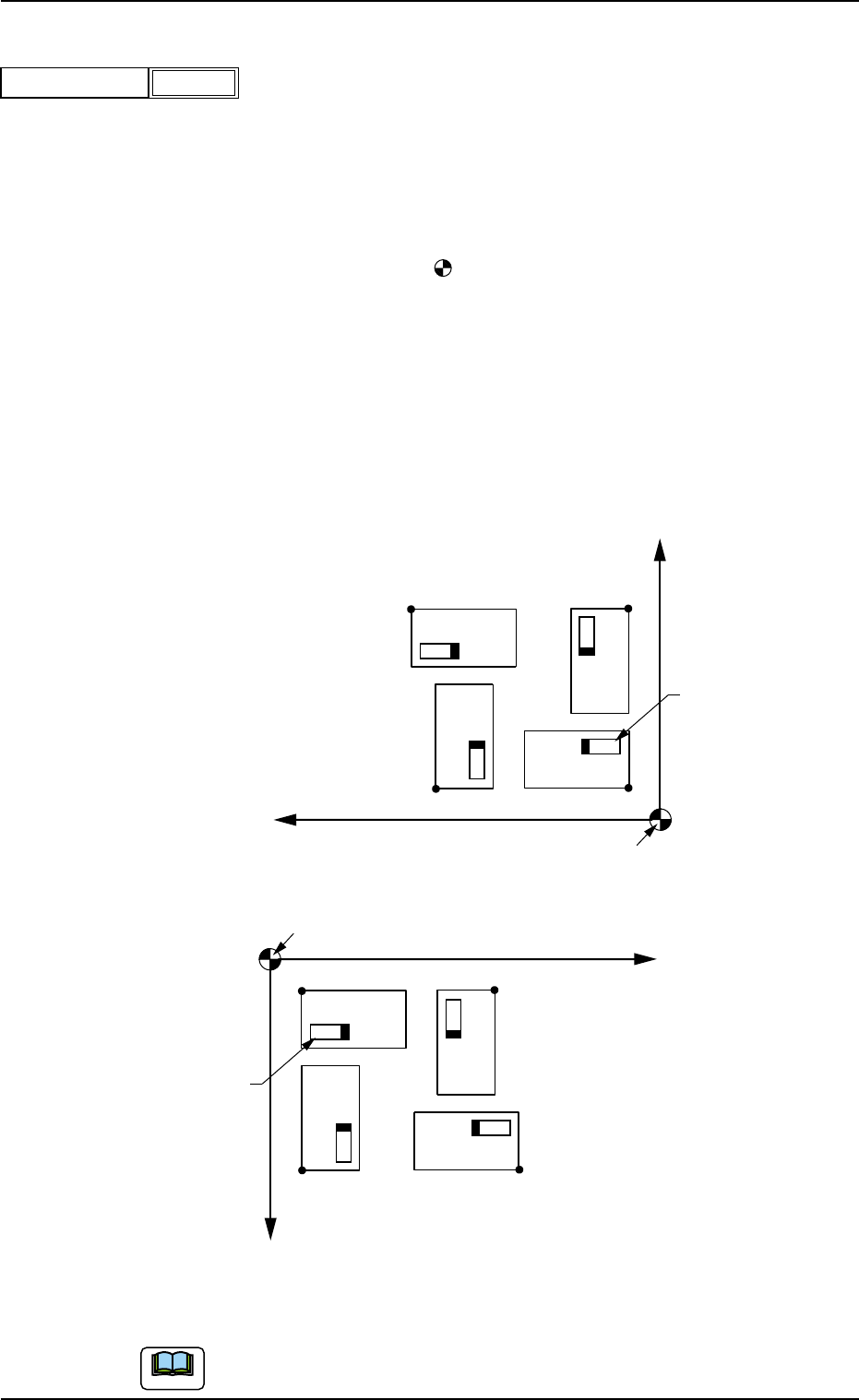
Set an angle of each pattern.
Keep the angle of the reference pattern as "000°00'".
In the figure below, "Pattern 1" is regarded as a reference one.
Unit: °(degree)
Data Input Range: +0°, +90°, +180°, or +270°
N
0
: The center of is the placement coordinate reference.
O
01
: Pattern Origin of Pattern 1
O
02
: Pattern Origin of Pattern 2
O
03
: Pattern Origin of Pattern 3
O
04
: Pattern Origin of Pattern 4
Pattern 1: 0° Pattern 2: 90°
Pattern 3: 180° Pattern 4: 270°
Fig. 3B117 Example of Repetitive Patterns
Do not set any angle in the last line (last step No.).
Keep it as "+000.00".
Placement Coordinate Reference (N0)
X
O
01
Component
Pattern 1
Pattern 3
Pattern 2
Pattern 4
O04
O03
O02
Y
Placement Coordinate Reference (N0)
X
O
01
Component
Pattern 1
Pattern 3
Pattern 2
Pattern 4
O04
O03
O02
Y
TCM-X110
TCM-X210 TCM-X300 TCM-X110M
2.5 Placement Data
0409-003 2-57 AIM01EDTP
Note
Fig. 3B116
+000.00
Z = theta [deg]
(C03_04) C
Enter some of the following control commands.
If a control command other than the following ones is used, the step
becomes invalid.
- (hyphen): This command handles the steps as those for compo-
nent placement.
S:This command invalidates the steps specified as those
for component placement.
C:This command invalidates the steps specified as those
for component placement.
Note : As for dispensers, these steps become valid.
D:This command handles the steps as those for compo-
nent placement.
Note : As for dispensers, these steps become invalid.
E:When placement data (O) is not created, this shows
the end of the steps in the placement data (P).
Confirm that "0" (zero) is set in the "X [mm]", "Y [mm]", "Z=theta", "B-X
[mm]" (option), and "B-Y [mm]" (option) and set "E".
(C03_05) Comment
Set a comment for each step No.
Up to 32 characters (alphanumerics and marks) can be used.
The automatic operation is not affected by these comments.
2.5 Placement Data
0412-002 2-58 AIM01EDTP
Note
Note
Fig. 3B118
-
C
-
Comment
Fig. 3B119
Notice
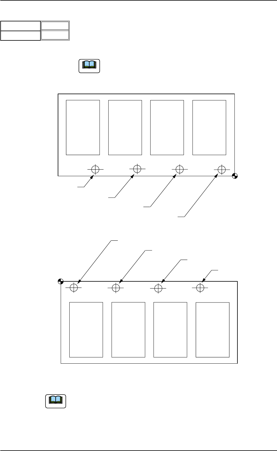
(C03_06) B-X [mm], B-Y [mm] (Option)
When "Enable" is set in the "Unit P.C.B. B.B.R." text box, it is required
to set the coordinates of each unit P.C.B. B.B.R. mark (each bad mark)
based on the placement coordinate reference N
0
.
Unit: mm
When the machine is not equipped with the unit P.C.B. B.B.R.
function (option), this function can not be used.
Fig. 3B121
(a) Refer to "2. Various Functions" in "Section 2" of "Volume 2: Opera-
tion (Supervisor)" for the unit P.C.B. B.B.R. detection function (op-
tion).
(b) Do not set any coordinates in the text boxes of the last line (last step
No.).
Keep them as "000.000".
Placement Coordinate
Reference (N
0
)
Bad Mark of Pattern 1
Bad Mark of Pattern 2
Bad Mark of Pattern 3
Bad Mark of Pattern 4
Pattern 4
(B-X
4
, B-Y
4
)
Pattern 3
(B-X
3
, B-Y
3
)
Pattern 2
(B-X
2
, B-Y
2
)
Pattern 1
(B-X
1
, B-Y
1
)
Placement Coordinate
Reference (N
0
)
Bad Mark of Pattern 1
Bad Mark of Pattern 2
Bad Mark of Pattern 3
Bad Mark of Pattern 4
Pattern 4
(B-X
4
, B-Y
4
)
Pattern 3
(B-X
3
, B-Y
3
)
Pattern 2
(B-X
2
, B-Y
2
)
Pattern 1
(B-X
1
, B-Y
1
)
TCM-X110
TCM-X210 TCM-X300 TCM-X110M
2.5 Placement Data
0404-002 2-59 AIM01EDTP
Fig. 3B120
B-X [mm]
B-Y
[mm]
000.000
000.000
Note
Note