3OM-996-005.pdf - 第304页
*2 X [mm], Y [mm] This is the offset data for the head rotational center based on the component recognition camera (Camera #1: high magnification) center of each head. Each head rotational center position is managed at S…
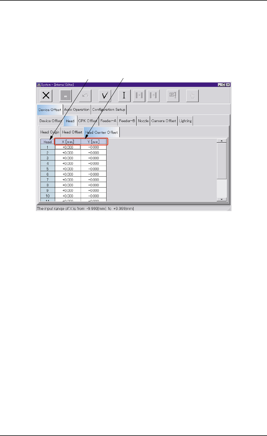
(3) "Head Center Offset" Tab
• Sheet Layout
When the "Head Center Offset" tab is pressed in the "Head" tab sheet,
the following tab sheet appears.
Fig. 3E23 "Head Center Offset" Tab Sheet
• Sheet Composition
*1 Head
The head Nos. are displayed.
0305-001 5-22
AIM01EDTP
*2
*1
3.2 "Device Offset" Tab
*2 X [mm], Y [mm]
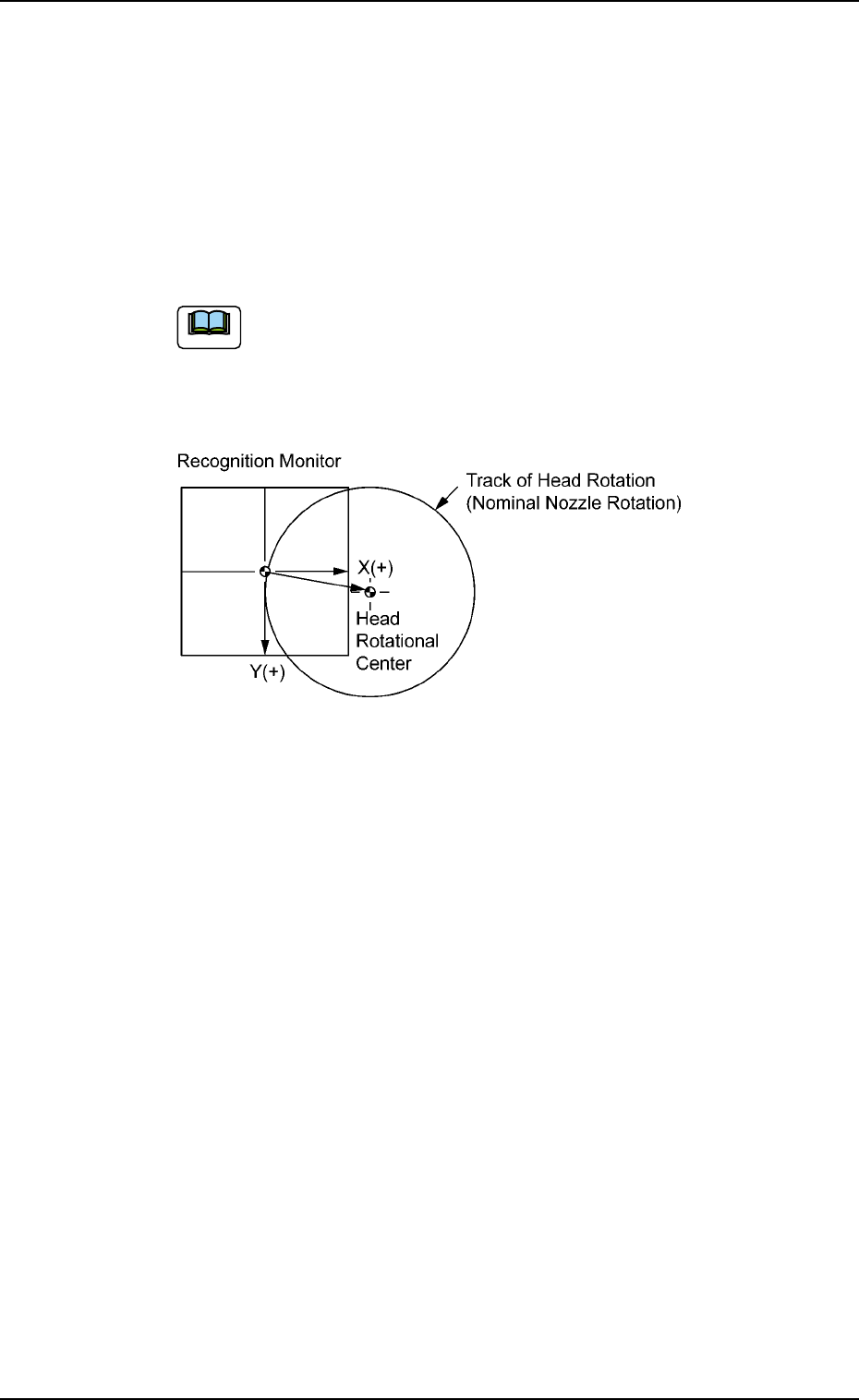
This is the offset data for the head rotational center based on the
component recognition camera (Camera #1: high magnification)
center of each head.
Each head rotational center position is managed at Station #3 (Com-
ponent Recognition) and plus and/or minus values are automati-
cally entered on the basis of the design values (X = 7.500 mm, Y =
0.000 mm).
(a) These offset values are automatically calculated through
teaching operation.
(b) These offset values are used for calculation of place-
ment position correction at component placement.
Fig. 3E24
0305-001 5-23
AIM01EDTP
3.2 "Device Offset" Tab
Note
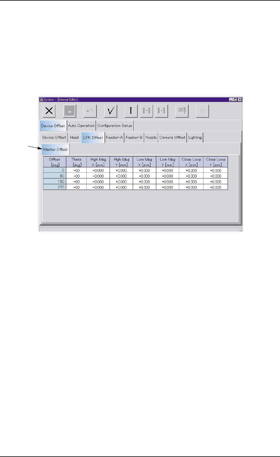
3.2.3 "CPK Offset" Tab
The "CPK Offset" tab sheet is composed of [Master Offset] tab.
• Sheet Layout
When the "CPK Offset" tab is pressed in the "Device Offset" tab sheet,
the following tab sheet appears.
Fig. 3E25
• Sheet Composition
*1 "Master Offset" Tab
When selected, the "Master Offset" tab sheet appears.
0305-001 5-24
AIM01EDTP
*1
3.2 "Device Offset" Tab