3OM-996-005.pdf - 第121页
(C02_06) H [mm] Set the height of components to be placed. (Reserved Data) unit: mm Fig. 3B103 Do not set any height in the last line (last P-No.). Keep it as "+0.000". (C02_07) Fdr . No. Set the Nos. of the fe…
(C02_05) Z
= =
= =
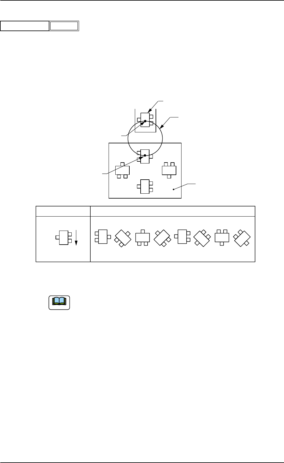
= theta [deg]
Set angles for component placement.
Unit: °(degree)
The placement angles must be determined according to the pack-
aged posture of components on the tape or the bulk feeder.
Example:
Fig. 3B101
Do not set any angle for component placement in the last line
(last P-No.).
Keep it as "+000.00".
Rotary Turret
90°
180°
270°
0°
Z
0° 45° 90° 135° 270°225°180°
315°
Packaged Posture
User Direction
of Feed
Packaged Posture of Component on
Tape Feeder
P.C.B.
Component Pick-Up Station
Component Placement Station
2.5 Placement Data
Note
0305-001 2-51 AIM01EDTP
Fig. 3B100
+000.00
Z = theta [deg]
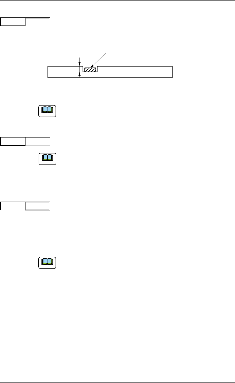
(C02_06) H [mm]
Set the height of components to be placed.
(Reserved Data)
unit: mm
Fig. 3B103
Do not set any height in the last line (last P-No.).
Keep it as "+0.000".
(C02_07) Fdr. No.
Set the Nos. of the feeders loaded with components.
(a) The feeder Nos. (Fdr Nos.) to be set here must be specified in the
placement feeder location data.
(b) Do not set any feeder No. in the last line (last step No.).
Keep it as "000".
(C02_08) V
Select one of the following options as the data for the local recogni-
tion mode.
00 : The local recognition is not performed.
01 : The local recognition (1-point recognition) is performed.
02 : The local recognition (2-point recognition) is performed.
(a) Be sure to set "Enable" in the "P.E.C. recognition mode
local" before specifying a parameter in the "V" text box.
Refer to "(A02_01) P.E.C. recognition function" in "Opera-
tion Data" for details.
(b) Refer to "(C02_11)", "(C02_12)", and "(C02_13)" for how
to specify the X and Y locations and the mark codes of the
local P.E.C. recognition mode.
P.C.B.
Component
Reference Plane
H
Note
Note
0305-001 2-52 AIM01EDTP
+0.000
H [mm]
Fig. 3B102
101
Fdr. No.
Fig. 3B104
2.5 Placement Data
Note
-
V
Fig. 3B105
(C02_09) C
Enter some of the following control commands.
If a control command other than the following ones is used, the step
becomes invalid.
- (hyphen) : This command handles the steps as those for com-
ponent placement.
S:This command invalidates the steps specified as those
for component placement.
C:This command invalidates the steps specified as those
for component placement.
Note: As for dispensers, these steps become invalid.
D:This command handles the steps as those for com-
ponent placement.
Note: As for dispensers, these steps become invalid.
E:When placement data (O) is not created, this shows
the end of the steps in the placement data (P).
P:This shows the end of the steps in the placement data
(P) of a repetitive pattern program.
Components are placed in normal sequence.
Q:This shows the end of the steps in the placement data
(P) of a repetitive pattern program.
Components are placed in reverse sequence.
B:When the unit P.C.B. B.B.R. detection function (op-
tion) must be used, set this control command in the
first step (P-No. 1).
See Note (a).
0, 1, 2, 3, 4, 5, 6, 7, 8, 9:
These control commands are used to enable the block
sorting function.
See Note (b).
(a) Do not set the B command in any lines except "P-No. 1".
Refer to "3.5 Repetitive Patterns (Unit P.C.B. B.B.R. Function En-
abled)" for concrete examples of the unit P.C.B. B.B.R. detection
function (option).
2.5 Placement Data
0412-002 2-53 AIM01EDTP
Note
C
Fig. 3B106
Notice