3OM-996-005.pdf - 第338页
0305-001 5-50 AIM01EDTP *8 Recog image save Mode, Object, Select, # of images, Head, Nozzle, Feeder No., Component ID Set parameters in the "Object", "Select", and "Save image size" text box…
*6 Nozzle message rate
Error counts [times], # of picks [times]
Set the parameters to show the nozzle No. whose pickup rate has
deteriorated during automatic operation.
When the number of picks has reached the specified value, the
parameter in the "Error counts [times]" text box is cleared.
When the number of pickup errors has reached the specified error
counts before the number of picks reaches the specified number of
picks, a warning message is issued as machine information.
(a) The number of picks and pickup errors is managed
for each feeder slot No. but the parameters in the "Er-
ror counts [times]" and "# of picks [times]" text boxes
are equally reflected on every feeder slot No.
(b) These parameters are not reflected on the automatic
nozzle bypass function. This is only for warning and
guidance.
(c) It is recommended that a comparatively short span be
specified.
(d) This function is provided to survey and avoid machine’s
malfunctions which may be caused during the start-
up operation of the machine.
(e) The data input range is "0 to 9999" (times) for both
"Error counts [times]" and "# of picks [times]"
(f) When "0" (zero) is set for "# of picks [times]" and "Er-
ror counts [times]" or the parameter in the "Error counts
[times]" text box is larger than the parameter in the "#
of picks [times]" text box, no warning message is is-
sued.
*7 Finished product interval (Reserved Data)
Mode, Interval [times]
This is one of the progress information messages displayed as ma-
chine information. When "Monitor" is set in the "Mode" text box, the
number of processed products can be monitored every time the
number of processed P.C.B.’s reaches the specified parameter in
the "Interval [times]" text box.
When "0" (zero) is set in the "Interval [times]" text box, the
number of processed products cannot be monitored.
0510-002 5-49
AIM01EDTP
3.3 "Auto Operation" Tab
Note
Note
0305-001 5-50 AIM01EDTP
*8 Recog image save
Mode, Object, Select, # of images, Head, Nozzle, Feeder No.,
Component ID
Set parameters in the "Object", "Select", and "Save image size" text
boxes to analyze the cause of a recognition error in comparison
with the error image on the monitor.
When "Save" is set in the "Mode" text box, the image which matches
the parameters in the "Object" and "Select" text boxes is stored in
memory of the recognition board. The image is stored at the resolu-
tion specified in the "Save image size" text box.
Mode
Select "Not Save", "Save (Recog NG)", or "Save (Recog OK)".
When "Save (Recog NG)" or "Save (Recog OK)" is set in the "Mode"
text box, the image which matches the parameters in the "Object"
and "Select" text boxes is stored in memory of the recognition board.
The image is stored at the resolution specified in the "# of images"
text box.
Do not select "Save (Recog OK)" for normal operations.
Object
When "Save (Recog NG)" or "Save (Recog OK)" is set in the "Mode"
text box, select "Cmpnt & P.E.C. Recog", "Cmpnt Recog", or "P.E.C.
Recog".
Select
When "Save (Recog NG)" or "Save (Recog OK)" is set in the "Mode"
text box, select "None", "Component ID", "Feeder", or "Head/Nozzle".
(a) When "Component ID" is selected, a component ID name
must be specified.
Refer to "• How to specify a component ID name" for de-
tails.
(b) When "Feeder" is selected, it is required to specify the
feeder No. in the "Feeder No." text box.
(c) When "Head/Nozzle" is selected, parameters must be set
in the "Head" and "Nozzle" text boxes.
(d) The parameter set in the "Select" text box becomes valid
only for those related to component recognition errors.
Setting of "Save image size" for P.E.C. recognition errors
becomes unconditional.
3.3 "Auto Operation" Tab
Note
Note
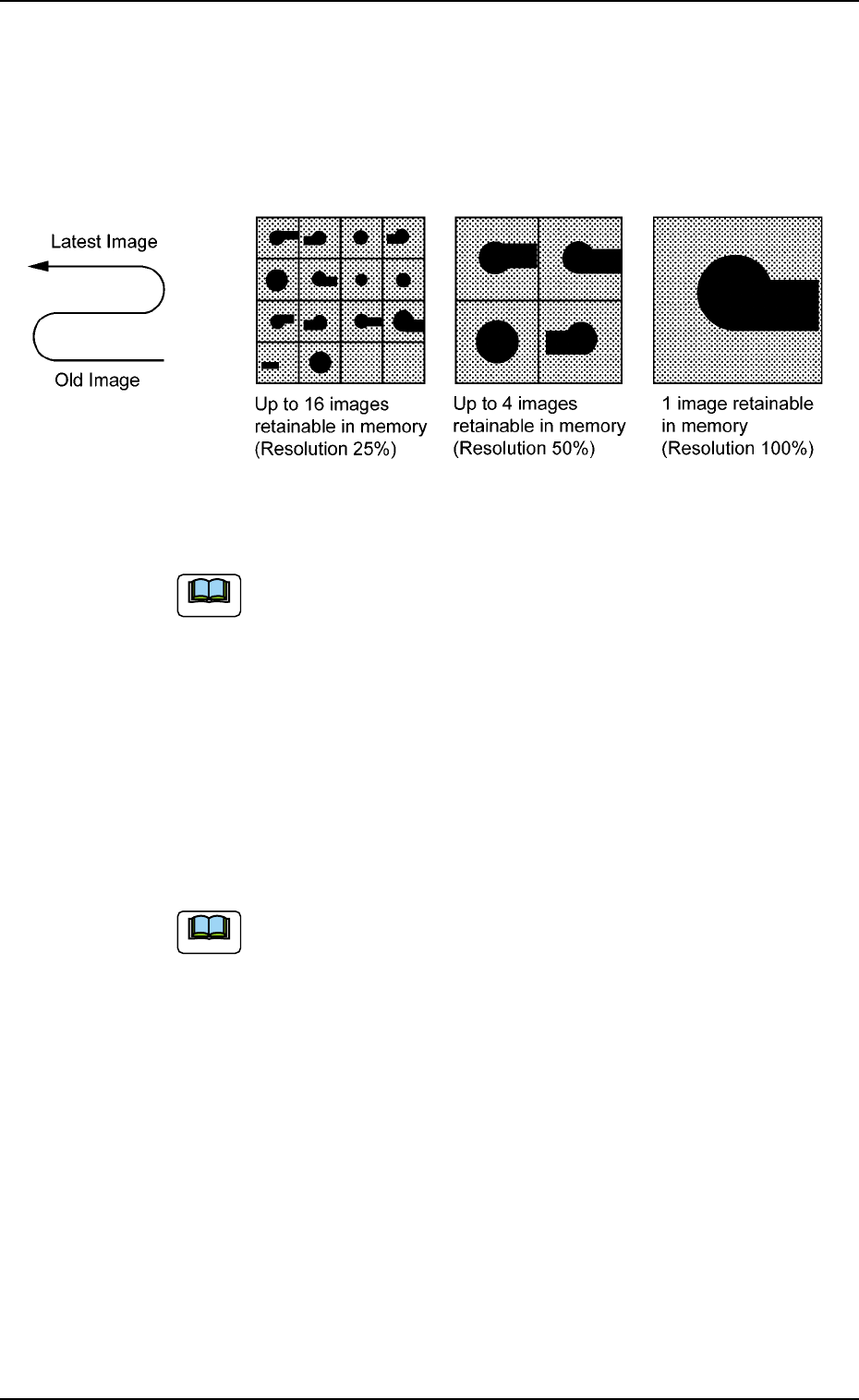
# of images
When "Save (Recog NG)" or "Save (Recog OK)" is set in the "Mode"
text box, select "1 (100% Resolution)", "4 (50% Resolution)", or "16
(25% Resolution)" as a proper resolution for the number of saved
images.
Fig. 3E43
The image data stored in memory is cleared when the
power switch of the machine is furned off.
*9 Trash box fill up warning mode
Notice, Stop
This function calculates the quantity of waste tape according to the
number of counts determined by the carrier data (tape feed, feed
pitch, type) in the component library data, issues a warning mes-
sage indicating that the trash box is full of waste tape, and performs
the stop operation of the machine.
When "0" is set in each text box, this function becomes
invalid.
The parameters specified here are reflected in the "Trash Box No-
tice" and "Trash Box Stop" text boxes in the "Warning Maint" tab
sheet of the "OPN. MODE" window (submenu) and in the "Notice"
and "Stop" text boxes in the "Trash Box" group box in the second
"Opn Mode" tab sheet of the "OPN. MODE" window (submenu).
0305-001 5-51
AIM01EDTP
3.3 "Auto Operation" Tab
Note
Note