3OM-996-005.pdf - 第358页
0403-002 5-70 AIM01EDTP *6 Lighting Mode Displayed are the lighting modes. *7 V-Groove Size [mm] Displayed are the V-groove sizes. *8 Camera Mag. Displayed are the camera magnification factors. • • • • • List of Paramete…
4.2 "Nozzle Data" Tab
The corresponding tab sheet enables the operator to set parameters to
be used for recognition of various types of nozzles. It is required to
register the nozzle data on the machine side before parameter settings.
• Sheet Layout
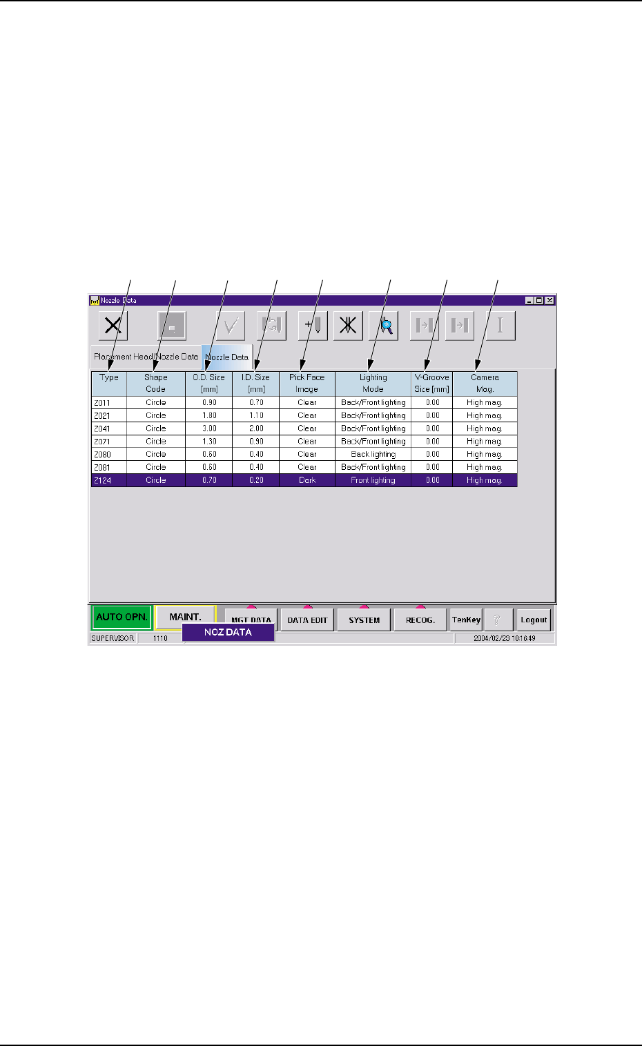
When the "Nozzle Data" tab is pressed in the "Nozzle Data" window,
the following tab sheet appears inside the window.
Fig. 3E58 "Nozzle Data" Tab Sheet
• Sheet Composition
*1 Type
Displayed are the nozzle types.
*2 Shape Code
Displayed are the shape codes of the nozzles.
*3 O.D. Size [mm]
Displayed are the outside diameters of the nozzles.
*4 I.D. Size [mm]
Displayed are the inside diameters of the nozzles.
*5 Pick Face Image
Displayed are the image properties of the nozzle's pick faces.
0403-002 5-69
AIM01EDTP
*1
*2
*3
*4
*5
*6
*7
*8
4.2 "Nozzle Data" Tab
0403-002 5-70 AIM01EDTP
*6 Lighting Mode
Displayed are the lighting modes.
*7 V-Groove Size [mm]
Displayed are the V-groove sizes.
*8 Camera Mag.
Displayed are the camera magnification factors.
••
••
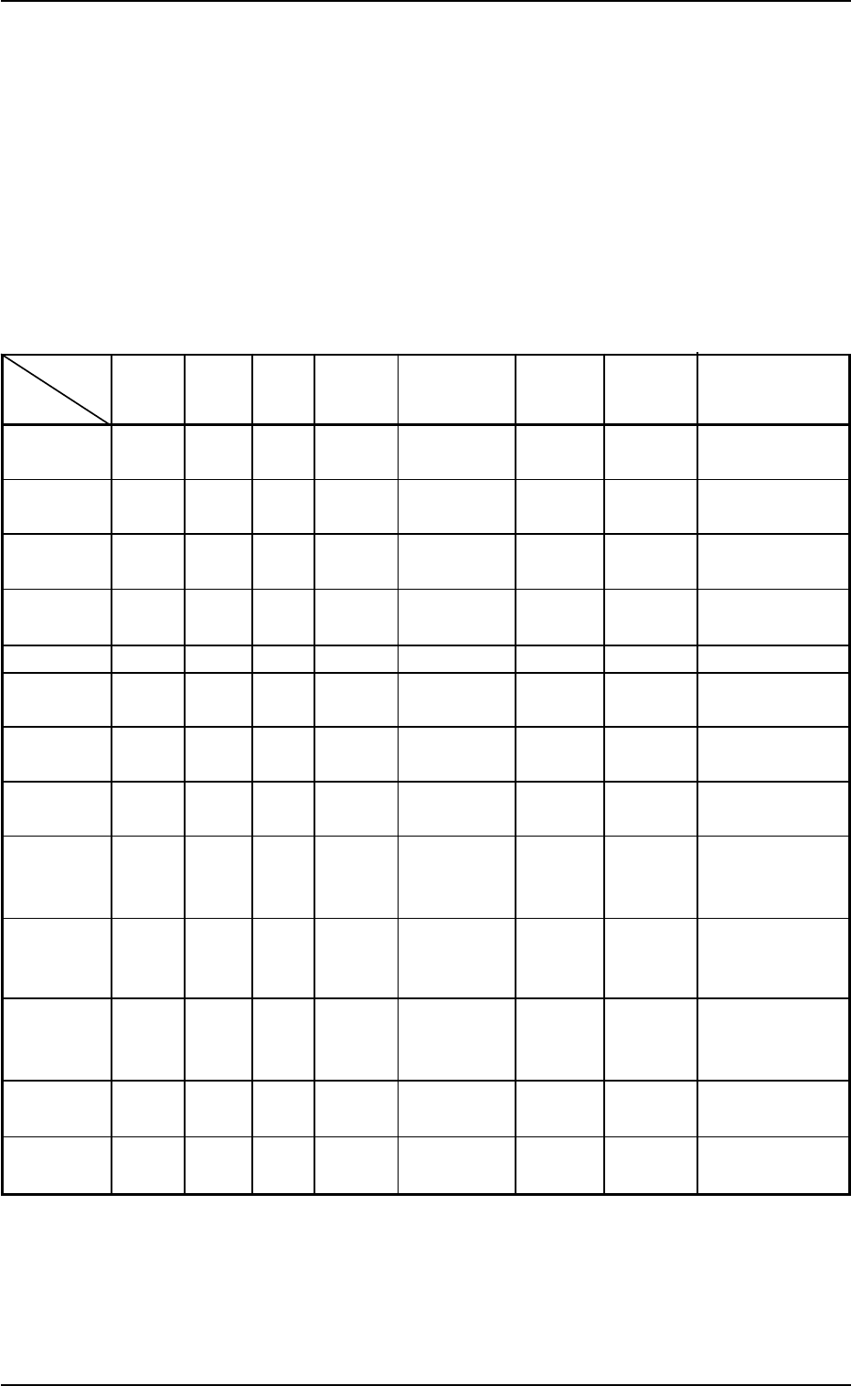
• List of Parameters
Table 3E2
4.2 "Nozzle Data" Tab
Shape
Code
Parame-
ter
O.D.
Size
[mm]
I.D. Size
[mm]
Pick
Face
Image
Lighting
Mode
V-Groove
Size
[mm]
Camera
Mag.
Remarks
Nozzle
Type
Z011
Z021
Z031
Z041
Z052
Z062
Z071
Z081
Z101
Z124
Z552
Z901
Z911
Circle
Circle
Circle
Circle
Circle
Circle
Circle
Circle
Circle
Circle
Circle
Circle
Circle
0.9
1.8
6.0
3.0
1.3
2.5
1.3
0.6
1.3
0.7
1.3
2.6
0.6
Clear
Clear
Clear
Clear
Clear
Clear
Clear
Clear
Dark
Dark
Clear
Clear
Clear
Back/Front
lighting
Back/Front
lighting
Back/Front
lighting
Back/Front
lighting
Back lighting
Back lighting
Back/Front
lighting
Back/Front
lighting
Front lighting
Front lighting
Back lighting
Back/Front
lighting
Back/Front
lighting
0.7
1.1
4.5
2.0
0.9
1.2
0.9
0.4
0.4
0.2
0.9
1.8
0.4
High mag.
High mag.
Low mag.
High/Low
mag.
High mag.
High mag.
High mag.
High mag.
High mag.
High mag.
High mag.
High mag.
High mag.
V-Groove
V-Groove
For Front
Lighting Recog-
nition
For Front
Lighting Recog-
nition
V-Groove
Exclusively used
for bulk feeders
For Special
Specifications
For Special
Specifications
0
0
0
0
0.7
1.0
0
0
0
0
0.7
0
0
(a) When a special nozzle is attached, the nozzle type data
must be registered.
(b) Refer to "4. Vacuum Nozzle Types" in "Section 1 (Vol. 2:
Operation (Supervisor))" for shape of each nozzle and ap-
plicable components.
(c) Be sure to enter the numerical values in Table 3E2 as out-
side diameters of Nozzles Z101 and Z124 for front lighting
recognition.
••
••
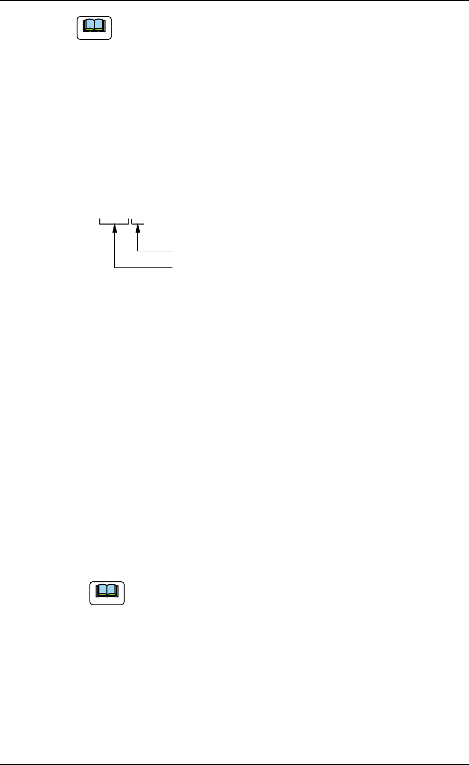
• Nozzle Type Names
The nozzle types are named based on the following regulations.
Z { { { (3 digits)
The last digit must be filled with 1 through 9.
01 to 89 : Group of Standard Nozzle Types
90 to 97 : Group of Special Nozzle Types
98 and 99 : Not used in actual cases. This digit
is prepared for a jig nozzle or a
dummy one.
There are some regulations on the last digit for the group of standard
nozzle types.
• "1" must be set for all prototypes.
• Whenever a prototype is modified for improvement and its identifi-
cation is required, numbers are allocated.
Example:
Z011 and Z012 (Temporary)
Both have almost no difference in their coverage of applicable com-
ponents because they belong to the group of nozzles having a
010th digit. However, "Z011" shows a prototype nozzle but "Z012"
means that some modification is made to the nozzle.
As for the group of the special type nozzles Z901 through
Z979, it does not make up a family.
Numbers are allocated sequentially and each type is differ-
ent.
4.2 "Nozzle Data" Tab
Note
0403-002 5-71 AIM01EDTP
Note