3OM-996-005.pdf - 第348页
*7 Output conveyor T imer #1 [sec], T imer #2 [sec], Stop timer (Buffer #1) [sec], Stop timer (Buffer #2) [sec] Timer #1 [sec] Set the time to limit the operating time (P .C.B. reception by the out- put machine) of the o…
0305-001 5-59 AIM01EDTP
Stop timer [sec]
Set the delay time (the period of time during which the sensor at the
buffer position of the input conveyor detects a P.C.B. and the con-
veyor stops) in the text box.
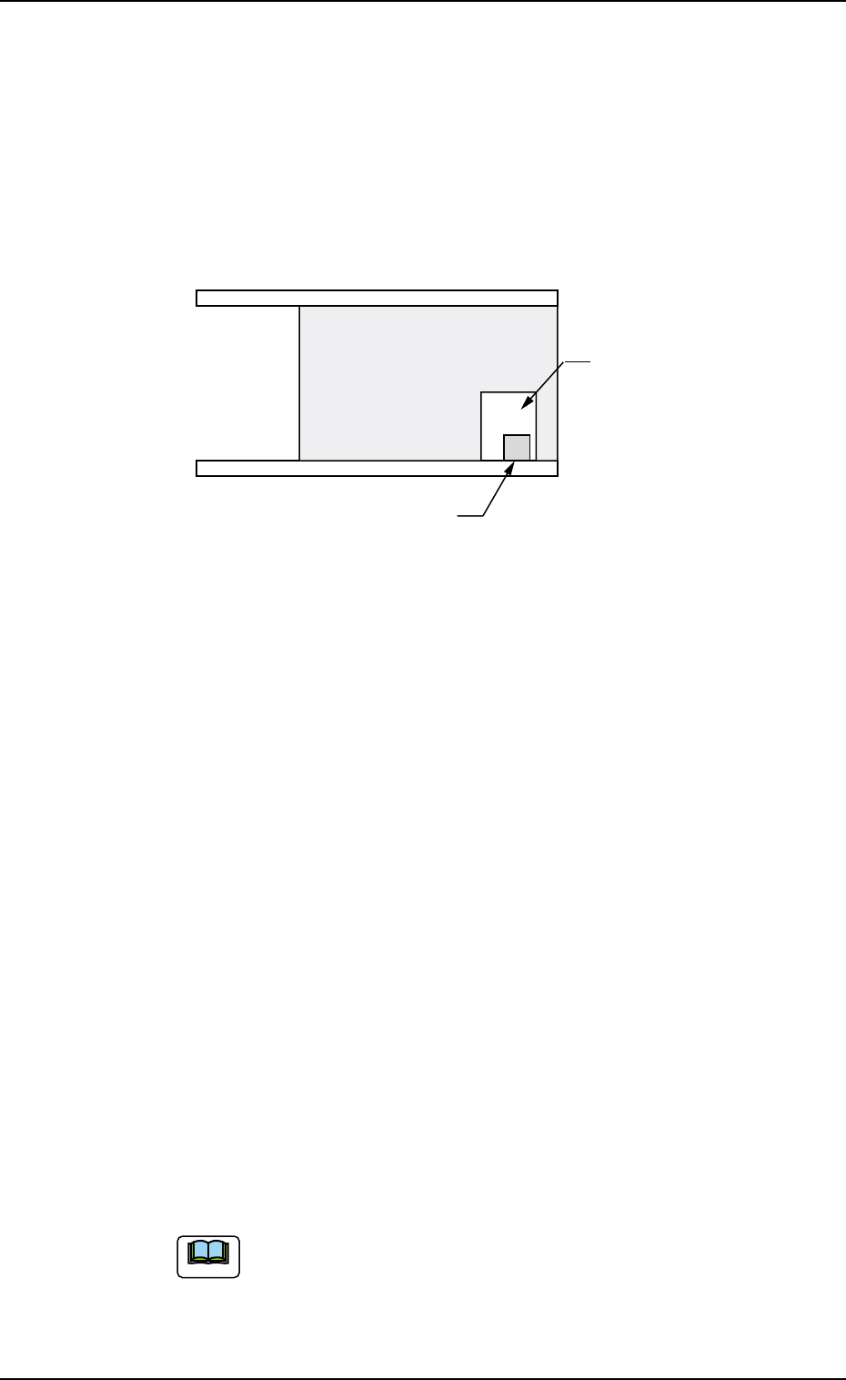
When a P.C.B. has a cutout as shown in the figure below and stops
at a position where the photosensor is located inside the cutout
after it is detected by the photosensor, the system determines it as
there is no P.C.B. To avoid this, it is required to set the delay time.
Fig. 3E50
*6 Output mode
Select "Standard", "Interval", or "SEMEMA" to determine how to
transfer a P.C.B. from the main machine to the output machine.
Standard
When the output machine is manufactured by us, set "Standard" in
the text box.
When the work request signal is received from the output machine,
the P.C.B. transfer signal of the machine is turned ON and a P.C.B.
is transferred to the output machine by the output conveyor.
When the work request signal is not turned OFF within the specified
time after a P.C.B. unloading action has started, the machine stops
in an error condition.
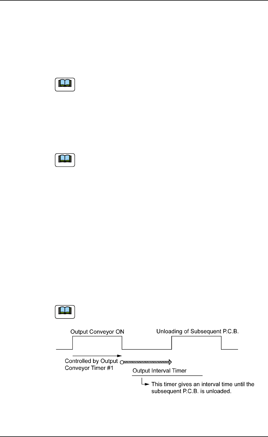
Interval
When the work request signal of the output machine is turned ON,
P.C.B.’s on the machine side are transferred to the output machine.
The conveyor stops when the output conveyor timer has reached
the specified time.
The machine starts its unloading actions when the unloading condi-
tion is fulfilled after the conveyor has stopped running and the time
specified in the "Output interval timer [sec]" text box has elapsed.
No error detection is made.
SMEMA (Not Available)
P.C.B.’s are transferred according to the "SMEMA" standard.
3.3 "Auto Operation" Tab
Photosensor
Cutout
P.C.B.
Note
*7 Output conveyor
Timer #1 [sec], Timer #2 [sec], Stop timer (Buffer #1) [sec], Stop
timer (Buffer #2) [sec]
Timer #1 [sec]
Set the time to limit the operating time (P.C.B. reception by the out-
put machine) of the output conveyor.
(a) Add 2 seconds (approx.) to the time required for P.C.B.
reception by the output machine and set the time in
the text box.
(b) The data input range is "0 to 99 seconds".
Timer #2 [sec]
Set the time to limit the operating time of the output conveyor to
transfer a P.C.B. on the main machine side.
The data input range is "0 to 99 seconds"
Stop timer (Buffer #1) [sec]
Set the delay time (the period of time during which the sensor at the
buffer 1 position of the output conveyor detects a P.C.B. and the
conveyor stops) in the text box.
Stop timer (Buffer #2) [sec]
Set the delay time (the period of time during which the sensor at the
buffer 2 position of the output conveyor detects a P.C.B. and the
conveyor stops) in the text box.
*8 Output interval timer [sec]
When "Interval" is set in the "Output mode" text box, set the time as
interval time for P.C.B. unloading actions.
The data input range is "0 to 99 seconds".
Fig. 3E51
0305-001 5-60 AIM01EDTP
3.3 "Auto Operation" Tab
Note
Note
Note
*9 Buffer conveyor counts [pcs.]
Set the number of P.C.B. buffers on the input conveyor in this text
box.
"1" or "2" can be set in the text box.
*10 # of Buffereds P.C.B.’s to be discharged [pcs.]
Set the number of P.C.B. buffers on the output conveyor in this text
box.
Set "1" or "2" in the "# of Buffereds P.C.B.’s to be discharged
[pcs.]" text box.
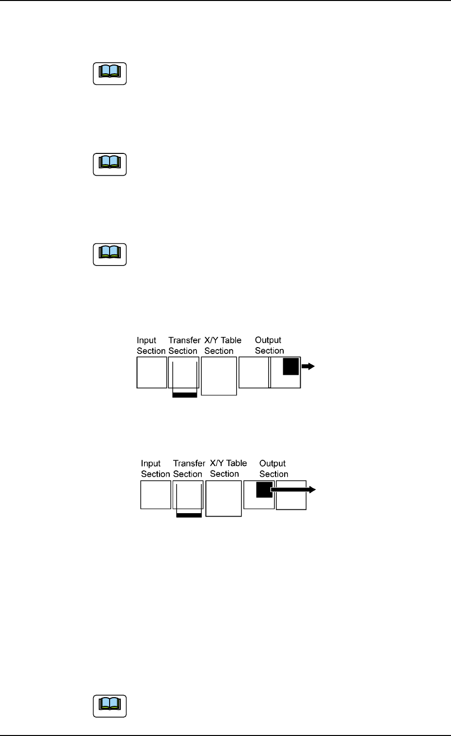
*11 P.C.B. output buffer position
Set "Outlet" or "Middle" as the P.C.B. buffer position for P.C.B. transfer
actions.
Fig. 3E52 and Fig. 3E53 show that the P.C.B. flow direc-
tion is "From Left to Right".
When the P.C.B. flow direction is "From Right to Left", the
reverse actions take place, compared with the figures.
Actions taken when "Outlet" is selected
Fig. 3E52
Action taken when "Middle" is selected
Fig. 3E53
*12 X/Y conveyor reverse stroke [mm]
Set the reverse stroke of the chute (X/Y) conveyor required when
the P.C.B. is transferred.
When the P.C.B. is fed over to the chute in the transfer operation,
the transfer claw might be kept away from the P.C.B.
The P.C.B. positioning will be completed normally by rotating the
chute (X/Y) conveyor in the reverse direction as much as the speci-
fied value to make the P.C.B. completely in contact with the transfer
claw.
Default (Value at Shipment): 5.0 mm
0305-001 5-61 AIM01EDTP
3.3 "Auto Operation" Tab
Note
Note
Note
Note