3OM-996-005.pdf - 第204页
3 .2 "Shape Data" T ab 3.2.1 "Mold Size" T ab The corresponding tab sheet appears when "Cylindrical", "Square", "De- form (Simple)", "IC (Simple)", "IC Com…

0510-002 3-16 AIM01EDTP
3.1 Toolbar and Icons
*2 Edit Sheet
This sheet enables the operator to edit the parameters of the se-
lected component ID.
3.2 "Shape Data" Tab
3.2.1 "Mold Size" Tab
The corresponding tab sheet appears when "Cylindrical", "Square", "De-
form (Simple)", "IC (Simple)", "IC Complex", "Connector (Simple)", "Con-
nector (Complex)", "Other Leaded (Simple)", or "Other Leaded (Com-
plex)" is selected in the "Component shape" text box.
• Sheet Layout
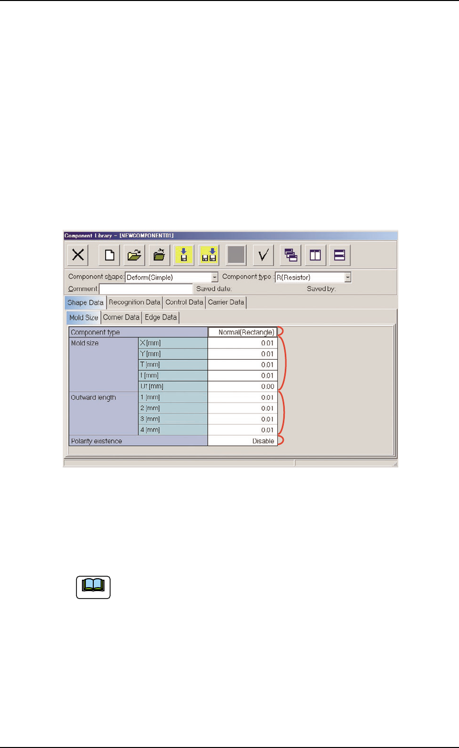
When the "Mold Size" tab is pressed in the "Shape Data" tab sheet,
the following tab sheet appears.
Fig. 3C13 "Shape Data" Tab Sheet ("Deform (Simple)" Selected)
• Sheet Composition
Each parameter is displayed or can be entered.
Refer to "4.1.3 Basic Usage of Text Boxes" for the detailed in-
formation on how to enter each parameter.
(1) Component shape: Cylindrical, Square
*2 Mold size, *4 Polarity existence
0510-002 3-17
AIM01EDTP
3.2 "Shape Data" Tab
*1
*2
*4
*3
Note

0305-001 3-18 AIM01EDTP
(2) Component shape: Deform (Simple)
*1 Component type, *2 Mold size, *3 Outward length,
*4 Polarity existence
(3) Component Shape: IC (Simple), IC (Complex),
Connector (Simple),
Connector (Complex),
Other Leaded (Simple),
Other Leaded (Complex)
*2 Mold size, *3 Outward length, *4 Polarity existence
3.2 "Shape Data" Tab