3OM-996-005.pdf - 第89页
(A01_09) P .C.B. transfer speed Select one of the following options as P .C.B. transfer speed at which a P .C.B. can be transferred from the input conveyor onto the X/Y table. Standard Low Speed 1 Low Speed 2 Low Speed 3…
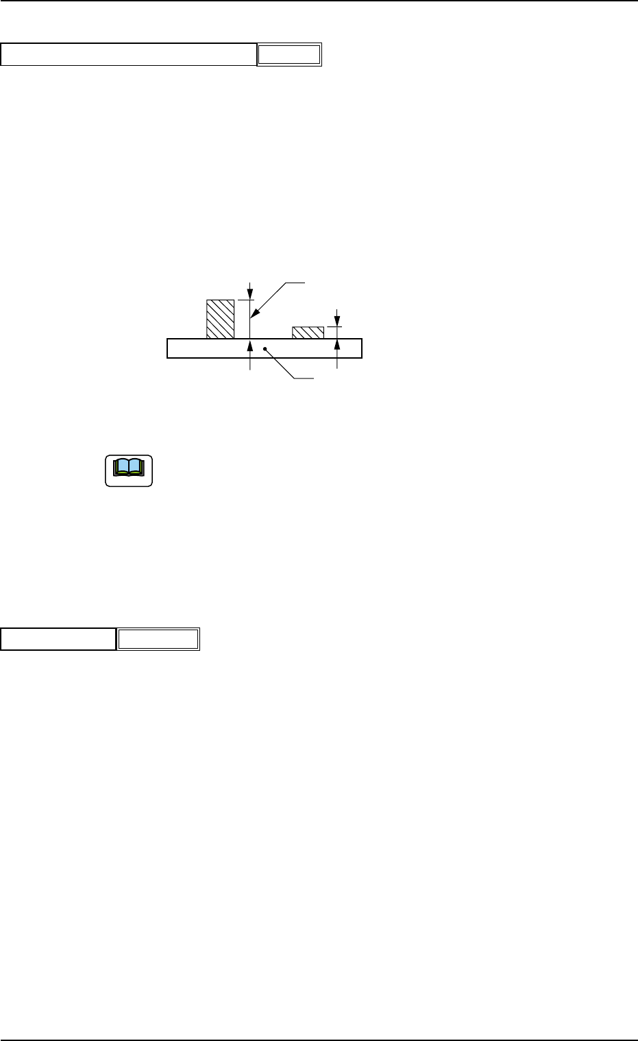
(A01_07) Pre-Placed component thickness
When some components are placed previously on a P.C.B. by the
input machine and transferred to the main machine, be sure to enter
the thickness of the tallest component of all in the text box.
Unit: mm
When components are not placed previously, set "00.000" (zero) in
the text box.
Data Input Range: 0.000 to 6.500
Fig. 3B23 State of Component Placement in Input Machine
(a) When components are placed previously and the main machine is
operated with "00.000" (zero) in this text box, some of the previously-
placed components may interfere with components to be placed
newly.
(b) It is advisable that placement data should be created such that shorter
components are placed before the tallest one.
(A01_08) Placement mode
Set "Placement" or "Pass" in the text box.
In normal cases, select "Placement".
When "Pass" is set in this text box and the pattern program data is
selected as current one, the vacuum pump and blower motors are
automatically turned off.
Note
P.C.B.
Set this thickness in the text box.
0510-002 2-19 AIM01EDTP
2.3 Operation Data
Placement
Placement mode
Fig. 3B24
0.000
Pre-Placed component thickness [mm]
Fig. 3B22

(A01_09) P.C.B. transfer speed
Select one of the following options as P.C.B. transfer speed at which a
P.C.B. can be transferred from the input conveyor onto the X/Y table.
Standard
Low Speed 1 Low Speed 2 Low Speed 3
High Speed 3 High Speed 2 High Speed 1
(a) In normal cases, select "Standard".
(b) When there are some previously-placed components,
the transfer speed can be decreased in advance to avoid
component deviations that may be caused by the P.C.B.
transfer.
(A01_10) Placement data sorting
Select one of the options as a placement sequence (order).
In normal cases, select "Standard".
Standard
Components are placed in the sequence specified by Control Com-
mand "P" (normal sequence) or "Q" (reverse sequence) in the place-
ment data.
Step
Components of the same feeder No. (Fdr No.) are placed consecu-
tively on unit P.C.B.’s (repetitive patterns) no matter which sequence
(normal or reverse sequence) is selected.
In normal cases, the feeder carriage moves less frequently, compared
with the case where "Standard" is set in the text box.
Note
0510-002 2-20 AIM01EDTP
2.3 Operation Data
Standard
P.C.B. transfer speed
Fig. 3B25
Standard
Placement data sorting
Fig. 3B26
(A01_11) Feeder standby position
Set a "Fdr No." (feeder slot No.) as a feeder standby position.
000 : This function is disabled.
Entry of "Fdr No." : After a piece of P.C.B. is finished, the feeder
carriage returns to the specified feeder slot
No. (Fdr No. = Pick-Up Position).
Data Input Range
TCM-X110 TCM-X210
101 to 179, 201 to 279, 301 to 379, 401 to 479
TCM-X110M
101 to 159, 201 to 259, 301 to 359, 401 to 459
TCM-X300
101 to 170, 201 to 270, 301 to 370, 401 to 470
Any feeder slot No. (Fdr No.) which does not exist in the placement feeder
location data cannot be specified.
(A01_12) Alternate mode
Select one of the following options to determine whether or not the
alternate function should be used.
Disable : The alternate function is disabled.
Unit Alternate : The unit alternate function is enabled.
Alternate Pallet : The pallet alternate function is enabled.
The feeder alternate function can be specified in the placement feeder
location data.
Note
0510-003 2-21 AIM01EDTP
2.3 Operation Data
000
Feeder standby position
Fig. 3B27
Alternate mode
Fig. 3B28
Disable
Note