OperationInstruction_Vsision XP.pdf - 第120页
Page 1 12 V ISION XP+ V AC 5 Software 5.5 The Masks Menu Operating Instructions V ersion 1.5 5.5.5 Conveyor V alues Fig. 5-4 3 Con veyor V a lues Setpoints can be entered here, and a ctual values can be displayed for the…
VISION XP+ VAC Page 111
5 Software
5.5 The Masks Menu
Operating Instructions
Version 1.5
I) Values for the gas outlet temperature monitoring thermo couple.
J) Temperature sensor
Temperature after Pyrolysis regulation.
K) Monitor
Monitoring/Protection of the heating element.
L) Pyrolysis On/Off
It indicates if Pyrolysis runs.
Note!
If the set values (default-values) are not preset over 210°C in at
least 2 Peak-zones, the pyrolysis heatings are not controlled. If the
set values are over 210°C in at least 2 Peak-zones, the pyrolysis
heatings are controlled automatically and the valve air or nitrogen
is open (depending on the switch position).
If the heating is switched off, the delay time is expired which lets
the air or the nitrogen flow further 5 min. in order that the pyrolysis is cooled
down.
Page 112 VISION XP+ VAC
5 Software
5.5 The Masks Menu
Operating Instructions
Version 1.5
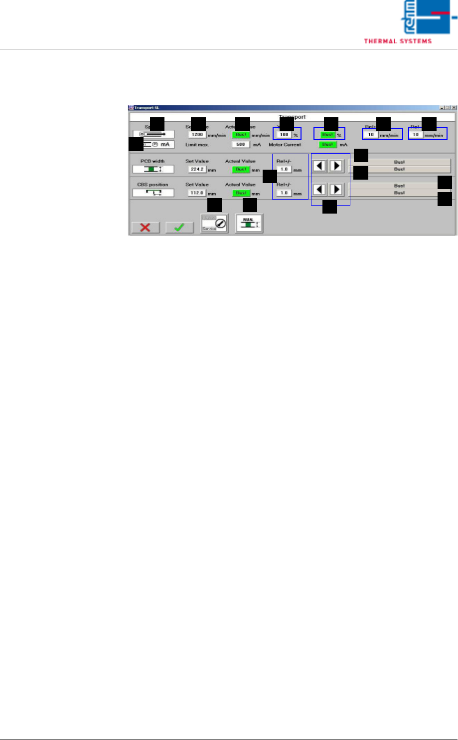
5.5.5 Conveyor Values
Fig. 5-43 Conveyor Values
Setpoints can be entered here, and actual values can be displayed for the
conveyor. In addition to this, tolerances and limits for manipulated variables
can be specified for the conveyor.
A) Designations of the individual functions
B) Setpoint
These fields are identical TO the entry fields in the Main Window, page
87.
C) Actual value
These fields are identical TO the display fields in the Main Window, page
87.
D) Ymax (setpoint limiting)
The maximum speed at which the drive unit is operated is puted in here
as a percentage.
E) Y (current setpoint)
The momentary manipulated variable is displayed.
F) Rel+
The relative upper tolerance limit can be changed here. If these values
are exceeded, the alarm message “Speed“ is generated.
G) Rel-
The relative lower tolerance limit can be changed here. If these values
are fallen short of, the alarm message “Speed“ is generated.
H) Rel+/-
The relative tolerance limit can be changed here. If it is exceeded or fall-
en short of, the system is not ready for operation.
I) Buttons for Adjusting Conveyor Width
For details refer to the Main Window, page 87.
J) Status display for the conveyor unit (= axis)
B
A
C D E F G
H
I
K
J
J
K
ML
N

VISION XP+ VAC Page 113
5 Software
5.5 The Masks Menu
Operating Instructions
Version 1.5
K) Status display of the limit switches
The failure „time out actual value“
The failure „time out actual value“ triggers off the alarm „transport adjust-
ment failure“ and can be reset over Alarm Reset
If the transport cannot be still moved automatically, please check the
transport mechanism. If automatic conveyor operation still isn't possible,
the conveyor system's mechanical components must be inspected.
L) Modes of operation
This field is identical with the field in the main screen.
M) Transport adjustment
This field is identical with the field in the main screen.
N) Conveyor drive current (option)
Momentary current values for the conveyor drive can be monitored here.
An alarm is triggered as soon as the setpoint is exceeded.