OperationInstruction_Vsision XP.pdf - 第124页
Page 1 16 V ISION XP+ V AC 5 Software 5.5 The Masks Menu Operating Instructions V ersion 1.5 5.5.7 Interfaces Fig. 5-4 6 Interfac e V alues for controlling the interfaces at the sy stem’s inlet and outlet are displayed h…
VISION XP+ VAC Page 115
5 Software
5.5 The Masks Menu
Operating Instructions
Version 1.5
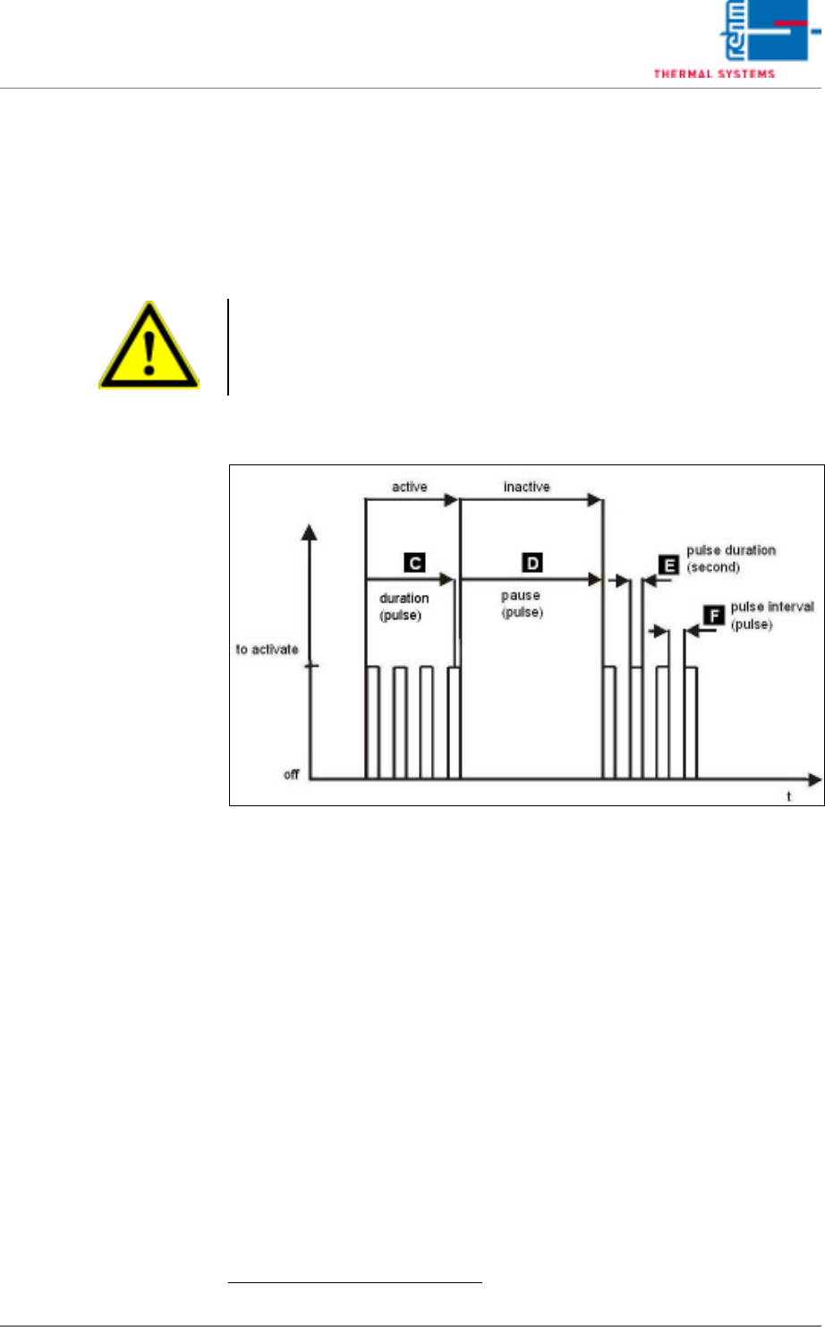
E) Pulse Duration
The duration of a single chain lubricator valve pulse can be selected
here. Duration is entered in seconds.
1
F) Interpulse Period
How much time elapses between chain lubricator valve pulses can be en-
tered here. Duration is entered in pulses.
1
Fig. 5-45 Activation chain lubricator
1.
Note!
The default settings are based upon empirical values. Due to the fact that
actual consumption depends on numerous factors, an individual setting
must be determined by the customer after initial system start-up.
Page 116 VISION XP+ VAC
5 Software
5.5 The Masks Menu
Operating Instructions
Version 1.5
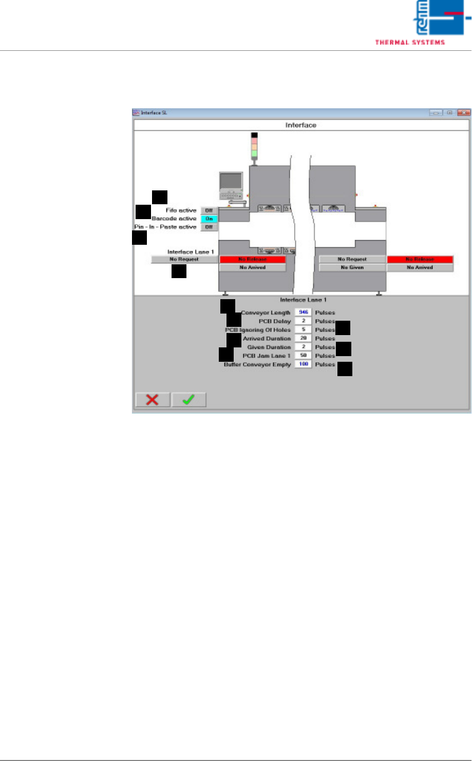
5.5.7 Interfaces
Fig. 5-46 Interface
Values for controlling the interfaces at the system’s inlet and outlet are
displayed here.
A) Belt Length
Number of pulses from the inlet to the outlet (determined at the factory).
B) PCB Delay
Number of pulses during which the light barrier must be obstructed be-
fore a PCB is detected.
C) PCB Hole Suppression
Distance specified for spanning holes in PCBs which do not obstruct the
light barrier (expressed in terms of pulses).
D) Arrival Duration
Number of pulses by which the “Arrival” signal is counted after the PCB
clears the light barrier at the inlet.
E) Discharge Duration
Number of pulses by which the “Discharge” signal is counted after the
PCB clears the light barrier at the outlet.
F) PCB jam lane 1
A number of impulses, after them the alarm „handing over pile-up“ is trig-
gered off when covering the outlet light barrier.
D
C
B
A
E
F
G
H
I
J
K

VISION XP+ VAC Page 117
5 Software
5.5 The Masks Menu
Operating Instructions
Version 1.5
G) Buffer Conveyor empty
After covering the inlet light barrier the transport adjustment for the sum
of conveyor length and buffer transport empty is decelerated. After enter-
ing 0, the function is deactivated. Is the value higher than „0“, the function
is active. With active function each board remains in the oven until it has
moved through the complete oven, plus the preset safety value. Indepen-
dently, if the board was deleted or reset manually only afterwards the
oven is unloaded.
H) Fifo (option)
It indicates if the PCB buffer at the outlet is active.
I) Barcode (option)
It indicates if the Barcode Scanner at the inlet is active.
J) Pin in Paste (option)
It indicates if the Pin in Paste-function is active.
K) No demand/demand at the inlet
It indicates that the preceding module wants to pass on the assembly
group to the oven.