OperationInstruction_Vsision XP.pdf - 第83页
Vision XP+ V AC Page 75 4 Equipment 4.10 Control Cabinets Operating Instructions V ersion 1.5 Control Cabin et, Section 2 Fig. 4-6 0 Con trol Cabine t, Sectio n 2 The second control cabinet hou ses the following com pone…
Page 74 Vision XP+ VAC
4 Equipment
4.10 Control Cabinets
Operating Instructions
Version 1.5
4.10 Control Cabinets
The control cabinets are located underneath the process chamber at the
front of the system. They are described beginning at the inlet.
Control Cabinet,
Section 1
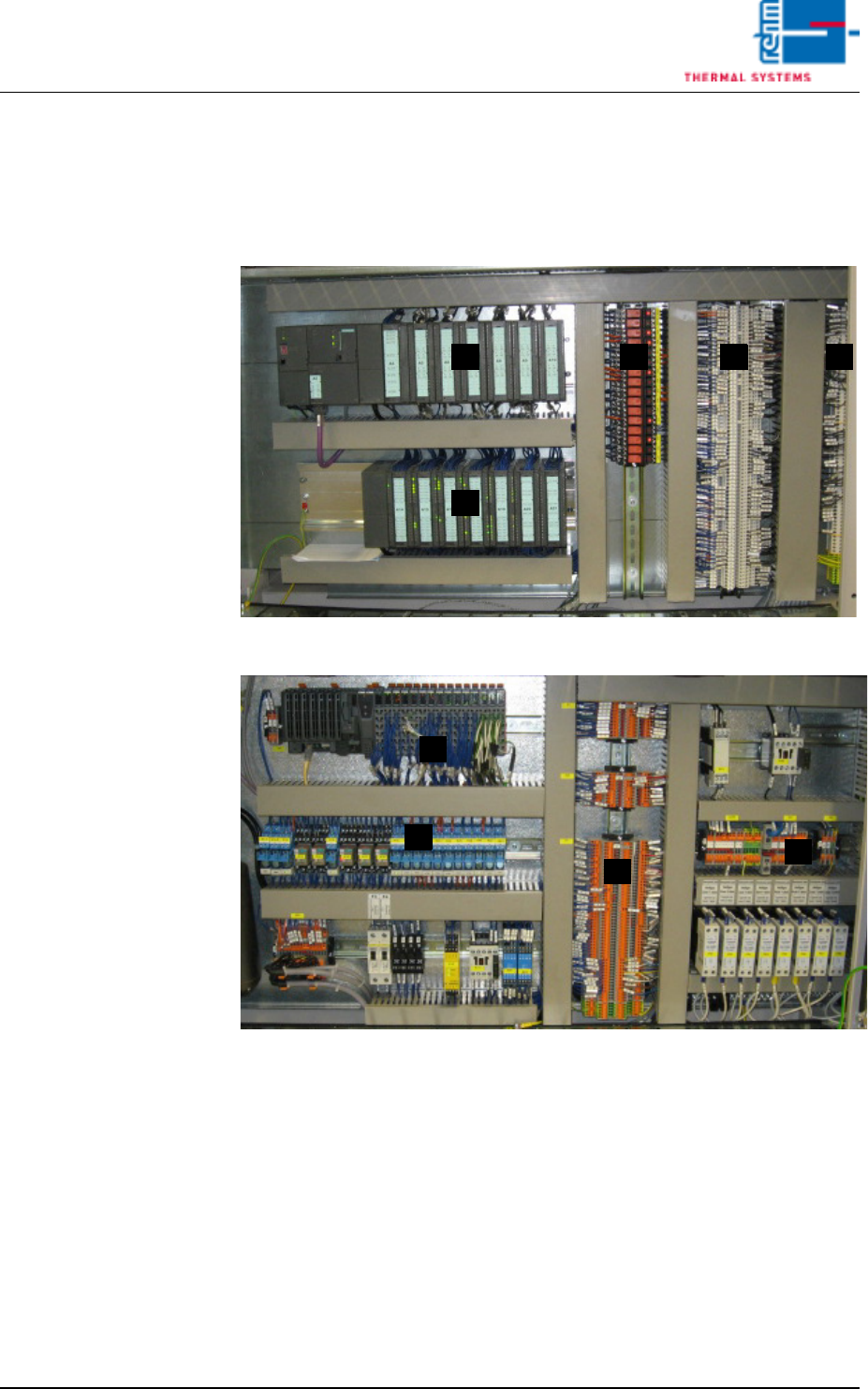
Fig. 4-58 Control Cabinet, Section 1 (with Siemens-control)
Fig. 4-59 Control Cabinet, Section 1 (with B&R-control)
The controller and the distributor terminals are located in the first control
cabinet. Either a Bernecker & Reiner (B & R) controller, or optionally a Sie-
mens controller, is installed to the cabinet.
A) controller and modules
B) 24V-relay
C) X1-clamps
D) X-24V-clamps und Xminus-clamps
BA C D
A
A
B
C
D
Vision XP+ VAC Page 75
4 Equipment
4.10 Control Cabinets
Operating Instructions
Version 1.5
Control Cabinet,
Section 2
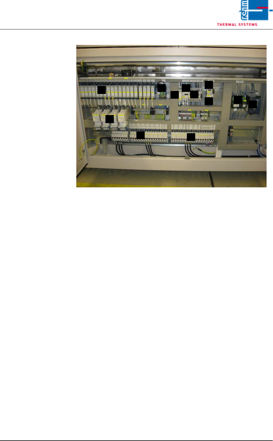
Fig. 4-60 Control Cabinet, Section 2
The second control cabinet houses the following components:
A) Solid-State relay
B) Current alarm module
C) Phase monitoring
D) Thermal Protector for motor
E) Lifting motor load relay (process chamber)
F) Water pump contactor
G) Thermal protector for the water pump
H) Power controller
I) Overcurrent monitoring
J) 24 V power pack
K) Fuse
C
B D
G
I
H
E
J
K
F
A
K
Page 76 Vision XP+ VAC
4 Equipment
4.10 Control Cabinets
Operating Instructions
Version 1.5
Control Cabinet,
Section 3
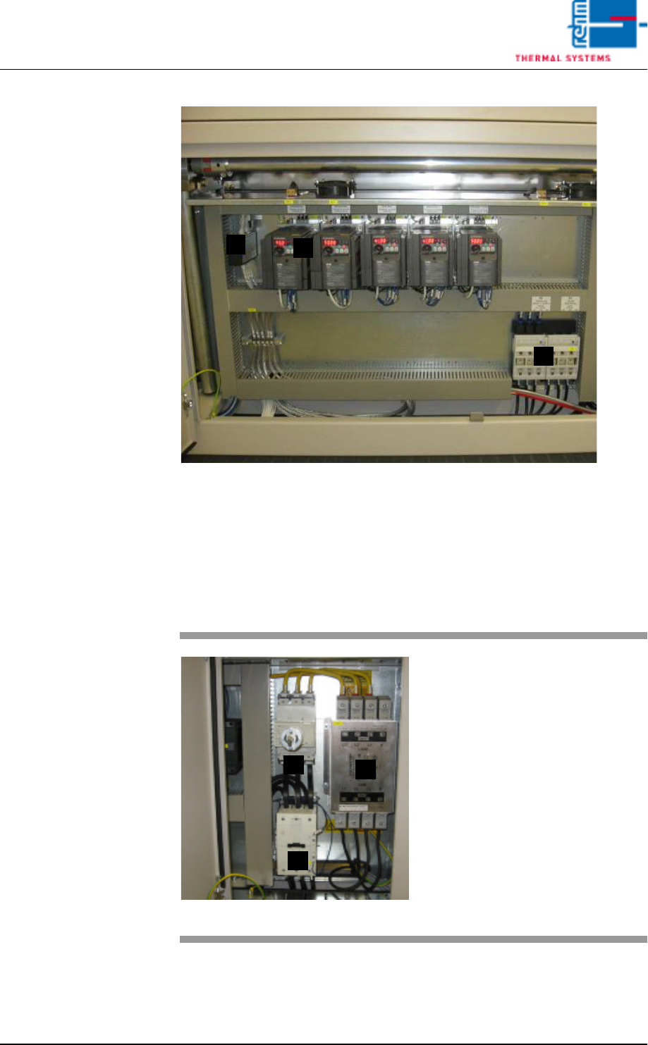
Fig. 4-61 Control Cabinet, Section 3
The third control cabinet houses the following components:
A) Frequency converter bus distributor
B) The frequency converter
C) Load break switch
Control Cabinet,
Section 4
C
A
B
Fig. 4-62 Control Cabinet, Section 4
The fourth control cabinet houses
the following components:
A) The mains switch
B) The heater contactor
C) The line filter
C
B
A