OperationInstruction_Vsision XP.pdf - 第51页
Vision XP+ V AC Page 43 4 Equipment 4.2 Display Elements and Controls on the System Operating Instructions V ersion 1.5 4.2.2 M ains Switch (option) 4.2.3 Eme rgency-Stop Buttons Note! Emergency-O ff-function Generally ,…
Page 42 Vision XP+ VAC
4 Equipment
4.2 Display Elements and Controls on the System
Operating Instructions
Version 1.5
4.2 Display Elements and Controls on the System
4.2.1 Mains Switch
Note!
Emergency-Off-function main switch
The main switch (Q1) is a superior safety-switch unit, over which the com-
plete system „OFF“ can be switched (disconnected from network). This
switch unit should only be activated, when there is a personal danger to life
and limb, as the PC and the fans of the heating and cooling zones will also
be switched off here.
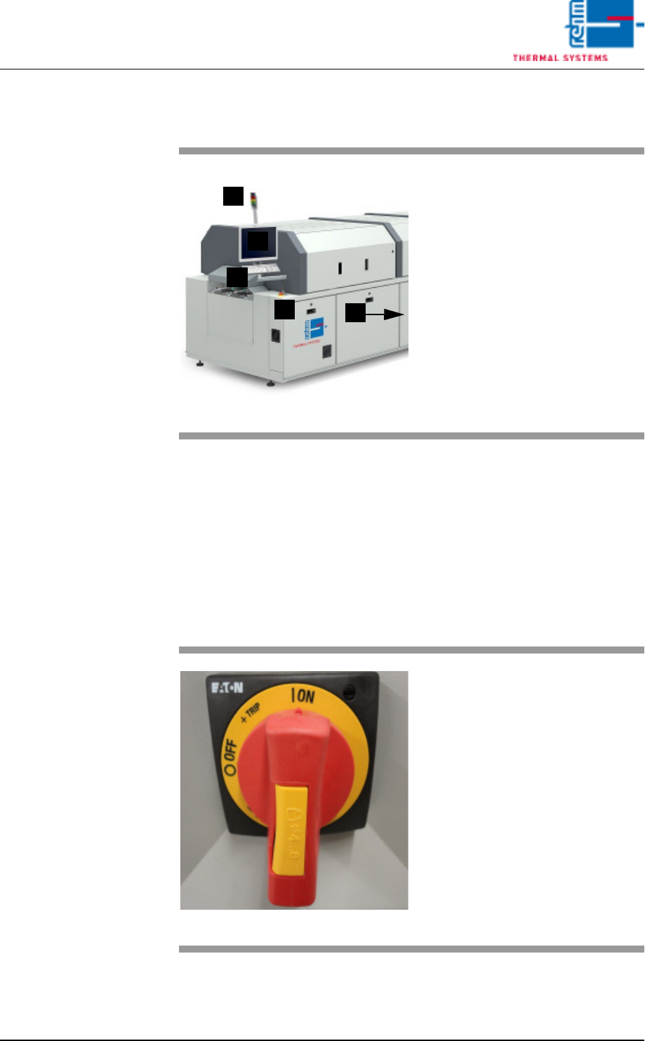
Fig. 4-2 Display Elements and Controls
A)Indicator lamp
B)Monitor screen
C)Keyboard
D)Emergency-stop buttons
E)Mains switch (red switch)
C
B
A
E
D
Fig. 4-3 Mains Switch
The mains switch is located at the
rear section on the operator side of
the machine.
It is only required for switching the
system’s power supply on and off
for service and maintenance work.
Caution! Life Endangering!
The mains switch is an integral part
of the power supply system. Even
when the mains switch is turned off,
certain components inside the sys-
tem still conduct life endangering
voltage.
Vision XP+ VAC Page 43
4 Equipment
4.2 Display Elements and Controls on the System
Operating Instructions
Version 1.5
4.2.2 Mains Switch (option)
4.2.3 Emergency-Stop Buttons
Note!
Emergency-Off-function
Generally, an emergency-off switch is used for avoidance of danger and in-
duces a save state of the machine.
When activating the Emergency-Off-switch (S10-S13) the system moves in
a save state, i.e. only PC and the fans of the heating and cooling zone are
operated to avoid their thermal damage. All heatings, the transport conveyor
and the transport adjustment, as well as the cooling circuit will be switched
off.
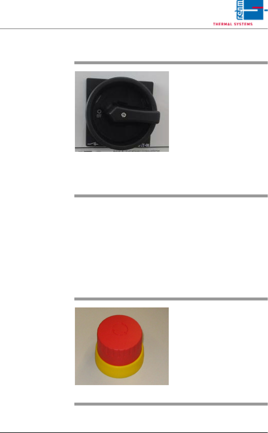
Fig. 4-4 Main switch
The mains switch is located at the
rear section on the operator side of
the machine.
It is only required for switching the
system’s power supply on and off
for service and maintenance work.
Caution! Life Endangering!
The mains switch is an integral part
of the power supply system. Even
when the mains switch is turned off,
certain components inside the sys-
tem still conduct life endangering
voltage.
Fig. 4-5 Emergency-Stop Buttons
The emergency-stop buttons have
been positioned such that they can
be readily accessed from any point.
The emergency-stop buttons snap
into place when actuated. Electrical
power is interrupted. The system is
depressurized. However, electrical
power is still supplied to the PC, the
monitor screen and the controls.
In order to release the button, it
must be rotated.
Page 44 Vision XP+ VAC
4 Equipment
4.2 Display Elements and Controls on the System
Operating Instructions
Version 1.5
4.2.4 Indicator Lamp
4.2.5 Industrial PC
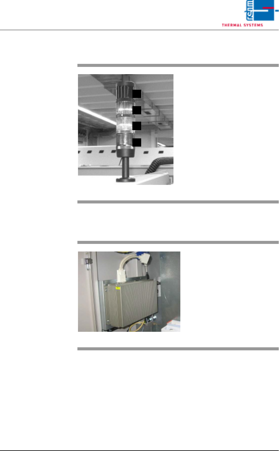
Fig. 4-6 Indicator Lamp
A)Horn
The horn sounds in the event of
severe malfunctions.
B)Group fault
Lights up when a fault occurs
which requires an intervention of
the operator.
C)Service mode operation
System is switched on, not ready
for operation
D)Ready for operation
Lights up when the system is
ready for operation.
D
C
B
A
Fig. 4-7 Industrial PC
Industrial PC´s are applied in all
Rehm – systems.