OperationInstruction_Vsision XP.pdf - 第86页
Page 78 Vision XP+ V AC 4 Equipment 4.13 Operating Hours Counter (optional) Operating Instructions V ersion 1.5 4.13 Operating Hours C ounter (optional) 4.14 Additiona l Heat Zo ne Monit oring (opt ional) Fig. 4-6 5 Oper…
Vision XP+ VAC Page 77
4 Equipment
4.11 Uninterruptible power supply VXP+ (option)
Operating Instructions
Version 1.5
4.11 Uninterruptible power supply VXP+ (option)
4.12 Transformer (option)
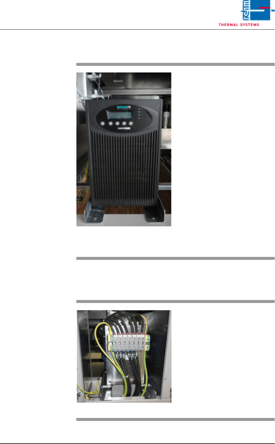
Fig. 4-63 USV
The UPS powers the PC, controller
and transport for approx. 15 min-
utes.
The following components have no
power during a power failure: heat-
er, heating fan, water pump, motor
for opening the chamber and the op-
tional exhaust air fan.
The machine must be switched off
at the master switch should the
power failure last longer than 15
minutes. The PC will autonomously
terminate any active programs.
The PC and UPS will switch off
completely after a certain time.
Note!
The user should not switch off the
PC separately.
The switch-off routine will not other-
wise execute correctly.
Fig. 4-64 Transformer
The transformer will be installed if
there is deviation of the input volt-
age of 230/400 V.
Page 78 Vision XP+ VAC
4 Equipment
4.13 Operating Hours Counter (optional)
Operating Instructions
Version 1.5
4.13 Operating Hours Counter (optional)
4.14 Additional Heat Zone Monitoring (optional)
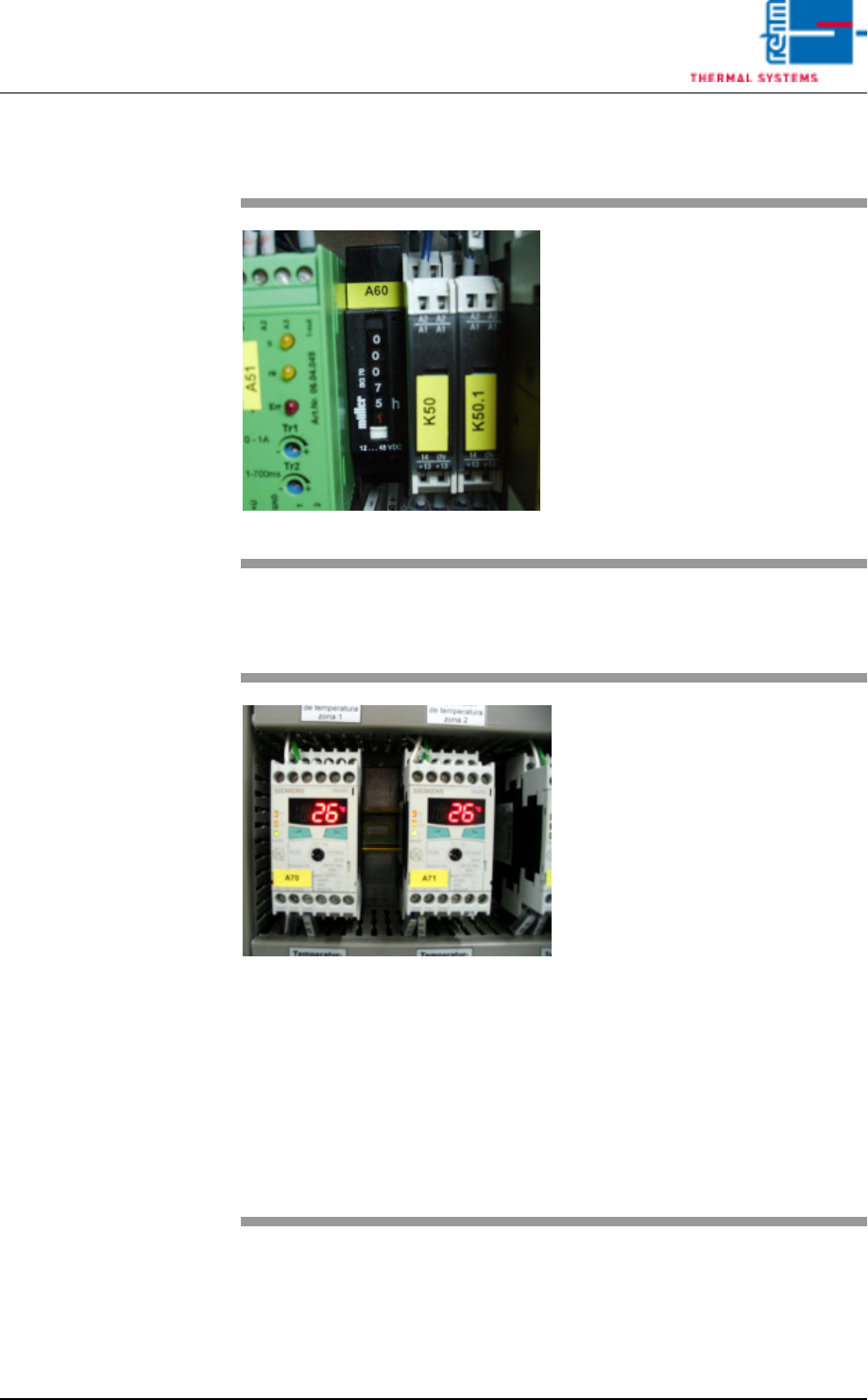
Fig. 4-65 Operating Hours Counter
The operating hours counter is lo-
cated in the second control cabinet.
Operating hours are displayed here,
during which the system has been
operated with the heat switched on.
Fig. 4-66 Additional Heat Zone Monitoring
A separate module can be installed
for each zone for the purpose of
hardware heat zone monitoring.
The module turns the heat off in the
event of an error. Refer to the
included operating instructions from
Siemens regarding settings for ad-
ditional heat zone monitoring.
Default values:
– Value 1: peak zone 360° C, pre-
heating zone 310° C
– Hysteresis: 5° C
– Delay time: 5 seconds
– Current principle:
normally closed
– Temperature mode:
when exceeded
– Sensor type: K
VISION XP+ VAC Page 79
5 Software
5.1 General Software Buttons and Setting
Operating Instructions
Version 1.5
5 Software
The individual software buttons, program menus and windows are explained
in this chapter. You will be guided through the required entries and software
functions.
Fewer functions may be included depending upon which system is used.
5.1 General Software Buttons and Setting
General Software
Buttons
The buttons listed below appear in numerous windows. The significance of
these buttons and their use is described here.
Fig. 5-1 OK Button
The current selection is acknowledged and/or saved
with the OK button.
Fig. 5-2 Yes Button
The current prompt is closed and the respective
action is executed when the Yes button is clicked.
Fig. 5-3 No Button
The current prompt is closed without executing the
respective action when the No button is clicked.
Fig. 5-4 Cancel Button
The current procedure is cancelled when the Cancel
button is clicked. The respective data are not saved
to memory.
Fig. 5-5 Delete Button
Selected (marked) data, products, programs etc. are
deleted when the Delete button is clicked.
Deletion cannot be undone.
Fig. 5-6 Save Button
Entered values or any other changes are saved to
memory when the Save button is clicked.
Previous entries are overwritten and cannot be
restored if they have not been saved to memory
elsewhere.
Fig. 5-7 Set Button
All setpoints which are visible in the current window
are transferred to the controller when the Set button
is clicked.