OperationInstruction_Vsision XP.pdf - 第79页
Vision XP+ V AC Page 71 4 Equipment 4.9 Nitrogen (optional) Operating Instructions V ersion 1.5 4.9 Nitrogen (optio nal) 4.9.1 L ayout of the Compressed Air and Nitrogen Unit Fig. 4-5 4 Comp ressed Ai r and N itrogen Un …
Page 70 Vision XP+ VAC
4 Equipment
4.8 Cooling System
Operating Instructions
Version 1.5
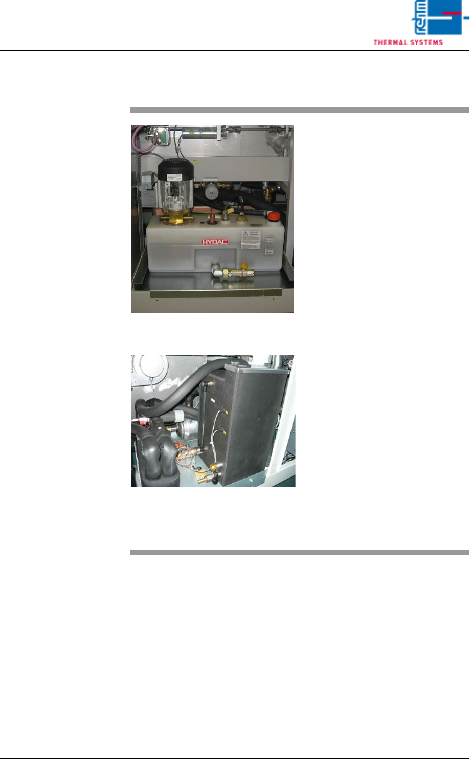
4.8 Cooling System
Fig. 4-52 Cooling system with integrated
coolant water pump
Fig. 4-53 Cooling system with integrated
coolant water pump CN
The cooling system is stored in a
tank made of plastic underneath the
last cooling zone.
Coolant water is pumped from the
coolant water tank into the coolant
circuits by a rotary pump.
The hot water subsequently flows
through the plate heat exchanger. It
is cooled down as a result, and is
then returned to the tank.
The level of the cooling water will be
controlled by means of two float
switch sensors.
One sensor monitors controlled the
minimum full-level. The sensor gen-
erates a „min. water level” message
which is displayed by the software
when the fill-level is too low. If the
fill-level drops below the second
sensor, it is assumed that the sys-
tem has a leak and the heat and the
water pump are shut down for safety
reasons.
An additional sensor monitors cool-
ant water temperature. It triggers
the „maximum temperature exceed-
ed” alarm message if the selected
upper limit is exceeded and
switched off the heating.
Vision XP+ VAC Page 71
4 Equipment
4.9 Nitrogen (optional)
Operating Instructions
Version 1.5
4.9 Nitrogen (optional)
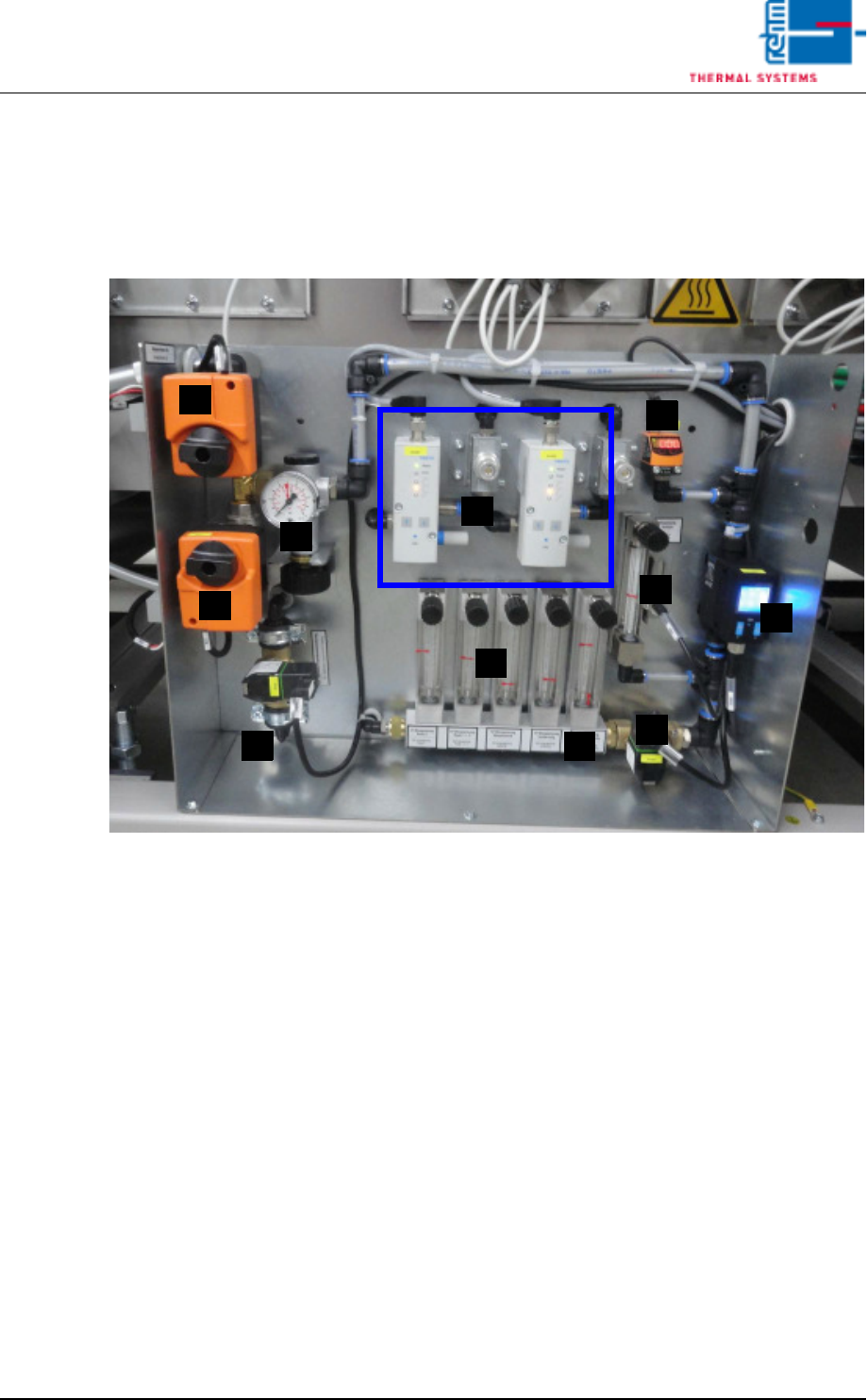
4.9.1 Layout of the Compressed Air and Nitrogen Unit
Fig. 4-54 Compressed Air and Nitrogen Unit
A) Pressure sensor
B) Nitrogen control
C) Isolation purge valve (pressure meter)
D) Flow meter / Pyrolysis with monitoring for venturi tube
E) Nitrogen switching (motor actuator)
F) Pressure gauge (behind the motor actuator)
G) Compressed air switching (motor actuator)
H) Nitrogen feed to process chamber (flow meter)
I) N2/O2 switch over valve
J) Purge valve process chamber
K) N2 usage indicator
F
A
E
H
G
K
D
J
C
B
I
Page 72 Vision XP+ VAC
4 Equipment
4.9 Nitrogen (optional)
Operating Instructions
Version 1.5
4.9.2 Scavenging Circuit
• When nitrogen supply is started up, the scavenging circuit is activated for
a period of approximately 45 minutes.
The purge valves (J) and the flow meter are opened for the specified period
of time. Nitrogen is blown into peak zones 1 and 3 and into lining. Also in the
nozzle holder for the VXP+
4.9.3 Distribution
• When the inert gas function is activated, nitrogen is fed to the various in-
jection points by a purge valve (J).
• Pressure is indicated at the pressure gauge (C).
• Consumption per hour is indicated by the flow meter (H).
• An alarm message is generated if the lower limit value selected for the
pressure sensor (A) is fallen short of.
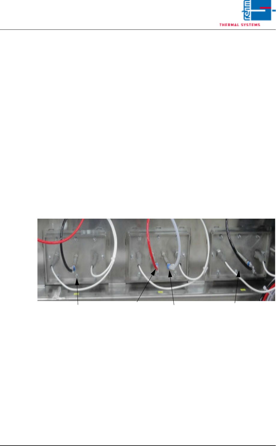
4.9.4 Connections of the nitrogen regulation
Fig. 4-55 N2 regulation
With the option „Nitrogen regulation“ the basic valve is connected in Peak
1+3. In Peak 2 the control valve is connected to the first connecting piece
and the analysis lead to the second one.
Peak 3
Peak 2
Peak 1
Analysis
Control valve
Basic valve
Basic valve